Industrial - Exlar
Benefits:Model | Frame Size mm (in) | Stroke mm (in) | Max Continuous Force kN (lbf) | Max Speed mm/s (in/s) |
KX60 | 60 (2.36) | 150 (6), 300 (12), 600 (24), 900 (36) | 6 (1,350) | 833 (32.8 ) |
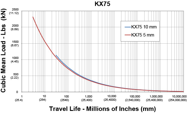
KX75 | 75 (2.95) | 150 (6), 300 (12), 600 (24), 900 (36) | 11.1 (2,500) | 666 (26.2) |
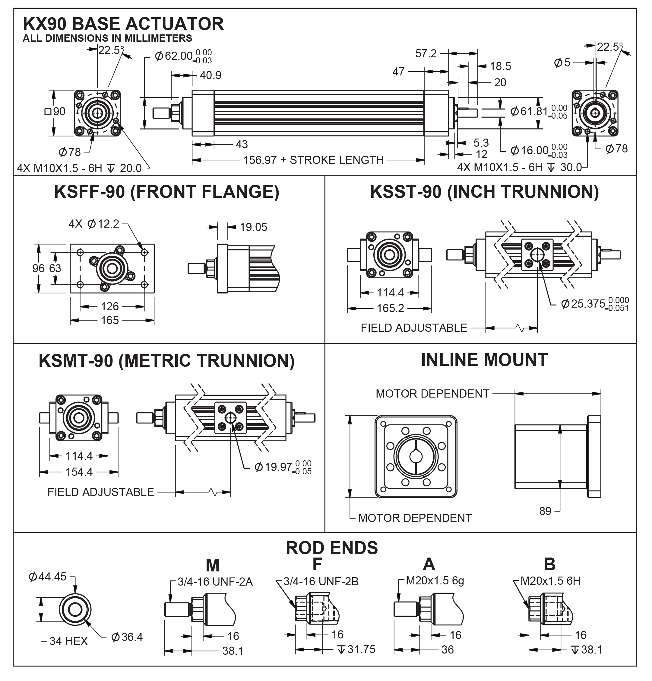
KX90 | 90 (3.54) | 150 (6), 300 (12), 600 (24), 900 (36) | 15.6 (3,500) | 500 (19.7) |
Roller screw actuators have several advantages over hydraulic or pneumatic actuators for many applications, especially those involving heavy loads and fast cycles. Other benefits include a small system footprint, long functional life, and low maintenance requirements. And because roller screw systems don’t require high-pressure fluid, they reduce noise levels and are not subject to potentially hazardous fluid leaks.
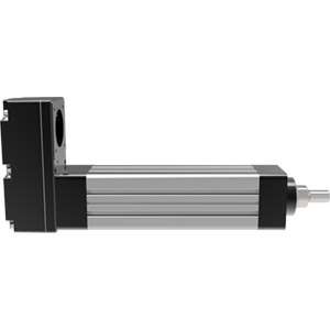
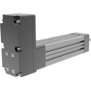
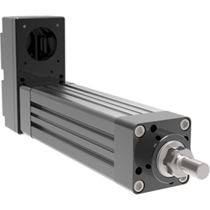
These robust electric actuators provide an ideal replacement for pneumatic cylinders and feature comparable dimensions with a similar form factor. Better performance, greater flexibility, and longer life culminate to make the K Series a smart choice for many applications. The high-performance planetary roller screw in the KX class offers performance that is far superior to competing actuator technologies. These compact electric linear actuators are ideal for applications from mobile equipment to hospital bed actuation, and many other demanding applications.
Other Advantages
Related Industries
Models: | KX60, KX75, KX90 (high capacity roller screw actuators) KM60, KM75, KM90 (standard capacity roller screw actuators) legacy product |
Frame Sizes: | 2.4, 3, 3.5 in (60, 75, 90 mm) |
Stroke Lengths: | 6 in (150 mm), 12 in (300 mm), 24 in (600 mm), 36 in (900 mm) |
Linear Speed: | up to 32.8 in/s (833 mm/s) |
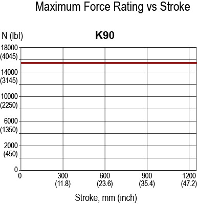
Maximum Force: | up to 3,500 lbf (15 kN) |
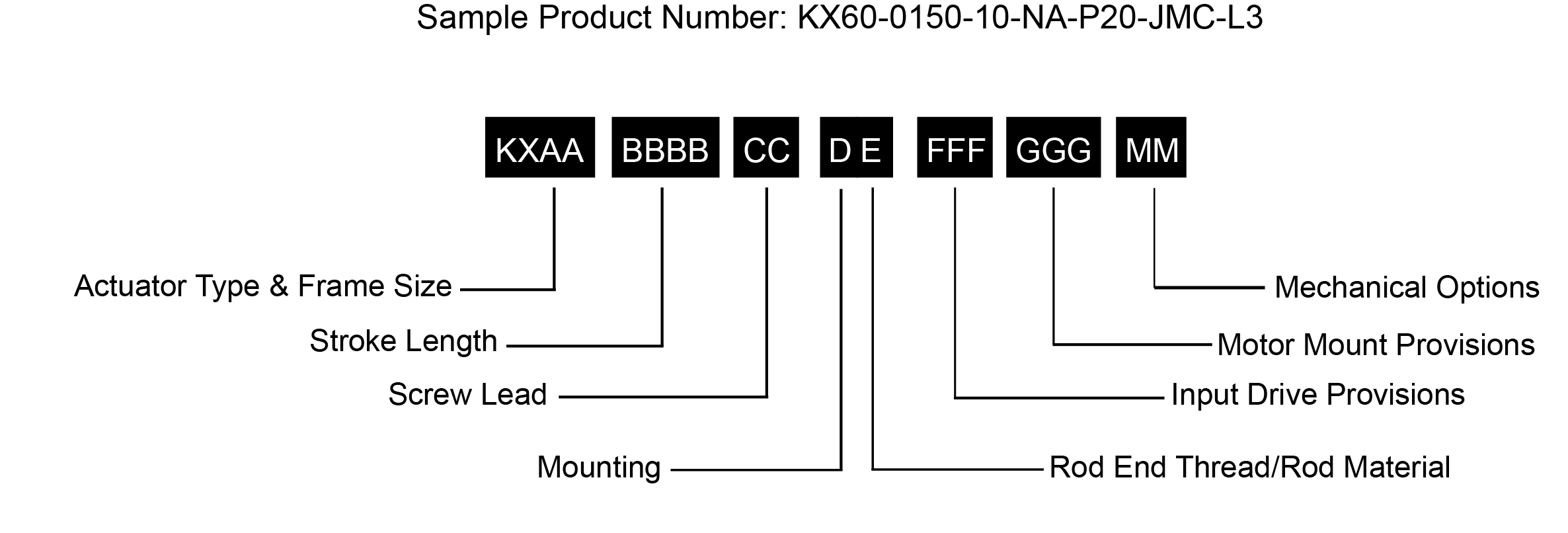
AA= Actuator Frame Size | FFF = Input Drive Provisions |
NOTES:
1. For oversized motors, contact your local sales representative.
2. For extended temperature operation consult factory for model number.
* Some options are not available with every configuration. For options or specials not listed above contact your local Exlar representative.
L1, L2, L3 = Adjustable External Travel Switch(es)
External travel switches indicate travel to the controller and are adjustable for either the home or end position.
Models | KX | KM - Legacy Product | |||
---|---|---|---|---|---|
Screw Lead | in | 0.1969 | 0.3937 | 0.1969 | 0.3937 |
mm | 5 | 10 | 5 | 10 | |
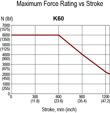
Maximum Force^2 | lbf | 1350 | 675 | 1350 | 675 |
kN | 6 | 3 | 6 | 3 | |
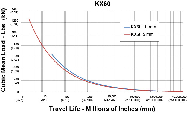
Life at Maximum Force | in x 10^6 | 1.6 | 18.2 | 0.4 | 4.5 |
km | 41.7 | 461.4 | 10.4 | 115.3 | |
C_a (Dynamic Load Rating) | lbf | 2738 | 2421 | 1725 | 1525 |
kN | 12.2 | 10.8 | 7.7 | 6.8 | |
Maximum Input Torque^1 | lbf-in | 53 | 53 | 53 | 53 |
Nm | 6 | 6 | 6 | 6 | |
Max Rated RPM @ Input Shaft | RPM | 5000 | 5000 | 5000 | 5000 |
Maximum Linear Speed @ Maximum Rated RPM | in/sec | 16.4 | 32.8 | 16.4 | 32.8 |
mm/sec | 417 | 833 | 417 | 833 |
kg-m^-2 (lbf-in-sec^-2) | kg-m^-2 (lbf-in-sec^-2) | |
---|---|---|
5 mm Lead | Add per 25 mm, 5 mm Lead | |
Base Unit - Input Drive Shaft Only | 1.480 x 10^-5 (1.31 x 10^-4) | 1.022 x 10^-6 (9.045 x 10^-6) |
Inline Unit - w/Motor Coupling | 2.702 x 10^-5 (2.39 x 10^-4) | 1.022 x 10^-6 (9.045 x 10^-6) |
10 mm Lead | Add per 25 mm, 10 mm Lead | |
Base Unit - Input Drive Shaft Only | 1.616 x 10^-5 (1.43 x 10^-4) | 1.173 x 10^-6 (1.038 x 10^-5) |
Inline Unit - w/Motor Coupling | 2.837 x 10^-5 (2.51 x 10^-4) | 1.173 x 10^-6 (1.038 x 10^-5) |
Parallel Drive Inertias (P10 Option) | ||
5 mm Lead | Add per 25 mm, 5 mm Lead | |
1:1 Reduction Parallel Belt Drive (66 mm) | 4.339 x 10^-5 (3.84 x 10^-4) | 1.022 x 10^-6 (9.045 x 10^-6) |
1:1 Reduction Parallel Belt Drive (86 mm) | 7.378 x 10^-5 (6.53 x 10^-4) | 1.022 x 10^-6 (9.045 x 10^-6) |
1:1 Reduction Parallel Belt Drive (96 mm) | 8.564 x 10^-5 (7.58 x 10^-4) | 1.022 x 10^-6 (9.045 x 10^-6) |
2:1 Reduction Parallel Belt Drive (96 mm) | 7.095 x 10^-5 (6.28 x 10^-4) | 2.555 x 10^-7 (2.261 x 1^-6) |
10 mm Lead | Add per 25 mm, 10 mm Lead | |
1:1 Reduction Parallel Belt Drive (66 mm) | 4.474 x 10^-5 (3.96 x 10^-4) | 1.173 x 10^-6 (1.038 x 10^-5) |
1:1 Reduction Parallel Belt Drive (86 mm) | 7.514 x 10^-5 (6.65 x 10^-4) | 1.173 x 10^-6 (1.038 x 10^-5) |
1:1 Reduction Parallel Belt Drive (96 mm) | 8.704 x 10^-5 (7.70 x 10^-4) | 1.173 x 10^-6 (1.038 x 10^-5) |
2:1 Reduction Parallel Belt Drive (96 mm) | 1.966 x 10^-5 (1.74 x 10^-4) | 2.931 x 10^-7 (2.595 x 10^-6) |
Parallel Drive Inertias (Smooth Motor Shaft Option) | ||
5 mm Lead | Add per 25 mm, 5 mm Lead | |
1:1 Reduction Parallel Belt Drive (66 mm) | 6.015 x 10^-5 (5.32 x 10^-4) | 1.022 x 10^-6 (9.045 x 10^-6) |
1:1 Reduction Parallel Belt Drive (86 mm) | 1.103 x 10^-4 (9.76 x 10^-4) | 1.022 x 10^-6 (9.045 x 10^-6) |
1:1 Reduction Parallel Belt Drive (96 mm) | 2.176 x 10^-4 (1.93 x 10^-3) | 1.022 x 10^-6 (9.045 x 10^-6) |
2:1 Reduction Parallel Belt Drive (96 mm) | 8.768 x 10^-5 (7.76 x 10^-4) | 2.555 x 10^-7 (2.261 x 10^-6) |
10 mm Lead | Add per 25 mm, 10 mm Lead | |
1:1 Reduction Parallel Belt Drive (66 mm) | 6.150 x 10^-5 (5.44 x 10^-4) | 1.173 x 10^-6 (1.038 x 10^-6) |
1:1 Reduction Parallel Belt Drive (86 mm) | 1.117 x 10^-4 (9.88 x 10^-4) | 1.173 x 10^-6 (1.038 x 10^-6) |
1:1 Reduction Parallel Belt Drive (96 mm) | 2.190 x 10^-4 (1.94 x 10^-3) | 1.173 x 10^-6 (1.038 x 10^-6) |
2:1 Reduction Parallel Belt Drive (96 mm) | 8.802 x 10^-5 (7.79 x 10^-4) | 2.931 x 10^-7 (2.595 x 10^-6) |
lb | kg | |
---|---|---|
Base Actuator Weight (Zero Stroke) | 3.7 | 1.7 |
Actuator Weight Adder (Per mm of Stroke) | 0.017 | 0.008 |
Adder for Inline (excluding motor) | 0.93 | 0.42 |
Adder for Parallel Drive (excluding motor) | 1.6 | 0.73 |
Adder for Front Flange | 0.93 | 0.42 |
Adder for Rear Clevis | 0.98 | 0.44 |
Adder for Two Trunnions | 0.72 | 0.33 |
Models | KX | KM - Legacy Product | |||
---|---|---|---|---|---|
Screw Lead | in | 0.1969 | 0.3937 | 0.1969 | 0.3937 |
mm | 5 | 10 | 5 | 10 | |
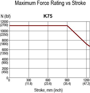
Maximum Force^2 | lbf | 2500 | 1250 | 2500 | 1250 |
kN | 11.1 | 5.6 | 11.1 | 5.6 | |
Life at Maximum Force | in x 10^6 | 2.4 | 22.6 | 0.6 | 5.6 |
km | 60.7 | 573.3 | 15.2 | 143.5 | |
C_a (Dynamic Load Rating) | lbf | 5746 | 4820 | 3620 | 3036 |
kN | 25.6 | 21.4 | 16.1 | 13.5 | |
Maximum Input Torque^1 | lbf-in | 98 | 98 | 98 | 98 |
Nm | 11 | 11 | 11 | 11 | |
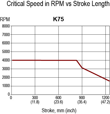
Max Rated RPM @ Input Shaft | RPM | 4000 | 4000 | 4000 | 4000 |
Maximum Linear Speed @ Maximum Rated RPM | in/sec | 13.1 | 26.2 | 13.1 | 26.2 |
mm/sec | 333 | 666 | 333 | 666 |
kg-m^-2 (lbf-in-sec^-2) | kg-m^-2 (lbf-in-sec^-2) | |
---|---|---|
5 mm Lead | Add per 25 mm, 5 mm Lead | |
Base Unit - Input Drive Shaft Only | 9.26 x 10^-5 (8.20 x 10^-4) | 3.13 x 10^-6 (2.77 x 10^-5) |
Inline Unit - w/Motor Coupling | 1.25 x 10^-4 (1.11 x 10^-3) | 3.13 x 10^-6 (2.77 x 10^-5) |
10 mm Lead | Add per 25 mm, 10 mm Lead | |
Base Unit - Input Drive Shaft Only | 9.48 x 10^-5 (8.39 x 10^-4) | 3.32 x 10^-6 (2.94 x 10^-5) |
Inline Unit - w/Motor Coupling | 1.44 x 10^-4 (1.28 x 10^-3) | 3.32 x 10^-6 (2.94 x 10^-5) |
Parallel Drive Inertias (P10 Option) | ||
5 mm Lead | Add per 25 mm, 5 mm Lead | |
1:1 Reduction Parallel Belt Drive (86 mm) | 2.29 x 10^-4 (2.03 x 10^-3) | 3.13 x 10^-6 (2.77 x 10^-5) |
1:1 Reduction Parallel Belt Drive (96 mm) | 3.19 x 10^-4 (2.82 x 10^-3) | 3.13 x 10^-6 (2.77 x 10^-5) |
1:1 Reduction Parallel Belt Drive (130 mm) | 5.96 x 10^-4 (5.28 x 10^-3) | 3.13 x 10^-6 (2.77 x 10^-5) |
2:1 Reduction Parallel Belt Drive (130 mm) | 2.82 x 10^-4 (2.50 x 10^-3) | 7.83 x 10^-7 (6.93 x 10^-6) |
10 mm Lead | Add per 25 mm, 10 mm Lead | |
1:1 Reduction Parallel Belt Drive (86 mm) | 2.31 x 10^-4 (2.05 x 10^-3) | 3.32 x 10^-6 (2.94 x 10^-5) |
1:1 Reduction Parallel Belt Drive (96 mm) | 3.21 x 10^-4 (2.84 x 10^-3) | 3.32 x 10^-6 (2.94 x 10^-5) |
1:1 Reduction Parallel Belt Drive (130 mm) | 5.98 x 10^-4 (5.30 x 10^-3) | 3.32 x 10^-6 (2.94 x 10^-5) |
2:1 Reduction Parallel Belt Drive (130 mm) | 2.83 x 10^-4 (2.51 x 10^-3) | 8.30 x 10^-7 (7.36 x 10^-6) |
Parallel Drive Inertias (Smooth Motor Shaft Option) | ||
5 mm Lead | Add per 25 mm, 5 mm Lead | |
1:1 Reduction Parallel Belt Drive (86 mm) | 2.84 x 10^-4 (2.51 x 10^-3) | 3.13 x 10^-6 (2.77 x 10^-5) |
1:1 Reduction Parallel Belt Drive (96 mm) | 4.25 x 10^-4 (3.76 x 10^-3) | 3.13 x 10^-6 (2.77 x 10^-5) |
1:1 Reduction Parallel Belt Drive (130 mm) | 7.33 x 10^-4 (6.48 x 10^-3) | 3.13 x 10^-6 (2.77 x 10^-5) |
2:1 Reduction Parallel Belt Drive (130 mm) | 3.32 x 10^-4 (2.94 x 10^-3) | 7.83 x 10^-7 (6.93 x 10^-6) |
10 mm Lead | Add per 25 mm, 10 mm Lead | |
1:1 Reduction Parallel Belt Drive (86 mm) | 2.86 x 10^-4 (2.53 x 10^-3) | 3.32 x 10^-6 (2.94 x 10^-5) |
1:1 Reduction Parallel Belt Drive (96 mm) | 4.27 x 10^-4 (3.78 x 10^-3) | 3.32 x 10^-6 (2.94 x 10^-5) |
1:1 Reduction Parallel Belt Drive (130 mm) | 7.35 x 10^-4 (6.50 x 10^-3) | 3.32 x 10^-6 (2.94 x 10^-5) |
2:1 Reduction Parallel Belt Drive (130 mm) | 3.33 x 10^-4 (2.94 x 10^-3) | 8.30 x 10^-7 (7.35 x 10^-6) |
lb | kg | |
---|---|---|
Base Actuator Weight (Zero Stroke) | 6.75 | 3.06 |
Actuator Weight Adder (Per mm of Stroke) | 0.0235 | 0.0107 |
Adder for Inline (excluding motor) | 2.46 | 1.12 |
Adder for Parallel Drive (excluding motor) | 4.06 | 1.84 |
Adder for Front Flange | 1.91 | 0.87 |
Adder for Rear Clevis | 1.85 | 0.84 |
Adder for Two Trunnions | 1.56 | 0.71 |
Models | KX | KM - Legacy Product | |||
---|---|---|---|---|---|
Screw Lead | in | 0.1969 | 0.3937 | 0.1969 | 0.3937 |
mm | 5 | 10 | 5 | 10 | |
Maximum Force^2 | lbf | 3500 | 1750 | 3500 | 1750 |
kN | 15.6 | 7.8 | 15.6 | 7.8 | |
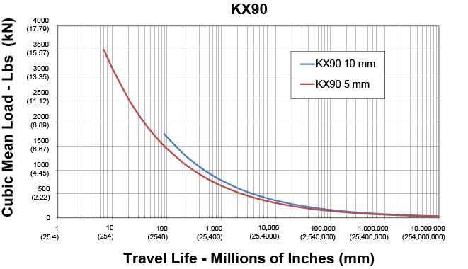
Life at Maximum Force | in x 10^6 | 7.1 | 90.4 | 1.8 | 22.6 |
km | 179.6 | 2295 | 44.9 | 573.8 | |
C_a (Dynamic Load Rating) | lbf | 11548 | 10715 | 7275 | 6750 |
kN | 51.4 | 47.7 | 32.4 | 30 | |
Maximum Input Torque^1 | lbf-in | 137 | 137 | 137 | 137 |
Nm | 16 | 16 | 16 | 16 | |
Max Rated RPM @ Input Shaft | RPM | 3000 | 3000 | 3000 | 3000 |
Maximum Linear Speed @ Maximum Rated RPM | in/sec | 9.8 | 19.7 | 9.8 | 19.7 |
mm/sec | 250 | 500 | 250 | 500 |
kg-m^-2 (lbf-in-sec^-2) | kg-m^-2 (lbf-in-sec^-2) | |
---|---|---|
5 mm Lead | Add per 25 mm, 5 mm Lead | |
Base Unit - Input Drive Shaft Only | 2.97 x 10^-4 (2.63 x 10^-3) | 1.11 x 10^-5 (9.80 x 10^-5) |
Inline Unit - w/Motor Coupling | 3.84 x 10^-4 (3.40 x 10^-3) | 1.11 x 10^-5 (9.80 x 10^-5) |
10 mm Lead | Add per 25 mm, 10 mm Lead | |
Base Unit - Input Drive Shaft Only | 3.00 x 10^-4 (2.66 x 10^-3) | 1.13 x 10^-5 (1.00 x 10^-4) |
Inline Unit - w/Motor Coupling | 3.87 x 10^-4 (3.43 x 10^-3) | 1.13 x 10^-5 (1.00 x 10^-4) |
Parallel Drive Inertias (P10 Option) | ||
5 mm Lead | Add per 25 mm, 5 mm Lead | |
1:1 Reduction Parallel Belt Drive (96 mm) | 5.12 x 10^-4 (4.53 x 10^-3) | 1.11 x 10^-5 (9.80 x 10^-5) |
1:1 Reduction Parallel Belt Drive (130 mm) | 7.98 x 10^-4 (7.07 x 10^-3) | 1.11 x 10^-5 (9.80 x 10^-5) |
2:1 Reduction Parallel Belt Drive (130 mm) | 3.41 x 10^-4 (3.02 x 10^-3) | 2.77 x 10^-6 (2.45 x 10^-5) |
10 mm Lead | Add per 25 mm, 10 mm Lead | |
1:1 Reduction Parallel Belt Drive (96 mm) | 5.15 x 10^-4 (4.56 x 10^-3) | 1.13 x 10^-5 (1.00 x 10^-4) |
1:1 Reduction Parallel Belt Drive (130 mm) | 8.02 x 10^-4 (7.10 x 10^-3) | 1.13 x 10^-5 (1.00 x 10^-4) |
2:1 Reduction Parallel Belt Drive (130 mm) | 3.42 x 10^-4 (3.03 x 10^-3) | 2.82 x 10^-6 (2.50 x 10^-5) |
Parallel Drive Inertias (Smooth Motor Shaft Option) | ||
5 mm Lead | Add per 25 mm, 5 mm Lead | |
1:1 Reduction Parallel Belt Drive (96 mm) | 6.18 x 10^-4 (5.47 x 10^-3) | 1.11 x 10^-5 (9.80 x 10^-5) |
1:1 Reduction Parallel Belt Drive (130 mm) | 9.35 x 10^-4 (8.27 x 10^-3) | 1.11 x 10^-5 (9.80 x 10^-5) |
2:1 Reduction Parallel Belt Drive (130 mm) | 3.91 x 10^-4 (3.46 x 10^-3) | 2.77 x 10^-6 (2.45 x 10^-5) |
10 mm Lead | Add per 25 mm, 10 mm Lead | |
1:1 Reduction Parallel Belt Drive (96 mm) | 6.21 x 10^-4 (5.50 x 10^-3) | 1.13 x 10^-5 (1.00 x 10^-4) |
1:1 Reduction Parallel Belt Drive (130 mm) | 9.38 x 10^-4 (8.30 x 10^-3) | 1.13 x 10^-5 (1.00 x 10^-4) |
2:1 Reduction Parallel Belt Drive (130 mm) | 3.92 x 10^-4 (3.47 x 10^-3) | 2.82 x 10^-6 (2.50 x 10^-5) |
lb | kg | |
---|---|---|
Base Actuator Weight (Zero Stroke) | 11.96 | 5.42 |
Actuator Weight Adder (Per mm of Stroke) | 0.0366 | 0.016 |
Adder for Inline (excluding motor) | 3.35 | 1.51 |
Adder for Parallel Drive (excluding motor) | 5.8 | 2.62 |
Adder for Front Flange | 3.4 | 1.54 |
Adder for Rear Clevis | 3.21 | 1.45 |
Adder for Two Trunnions | 1.768 | 0.8 |
Find more resources in our InfoCenter.
Below is the maximum-allowable duty cycle for your application given the percentage of input current over the continuous current rating:
For example: If your actuator has a continuous current rating of 10 A and a continuous force rating of 1000 lbf, this means it will take about 10 A to produce 1000 lbf of force, or 5 A to produce 500 lbf of force, and so on. What if you need to push more than 1000 lbf? In most cases, you would look at a stronger stator or a larger actuator. What if it’s only for a few seconds? Could you over-work the current actuator? Well the answer is yes, and calculating by how much isn’t too difficult.
Let’s say you need to push 1500 lbf. This would be equivalent to 1.5x the continuous current rating of 10 A. If you look below, the graph recommends no more than a 22% duty cycle in this case. This means you can run the actuator 22% of the time at 15 A without overheating. The other 78% of the time, it needs to be off/cooling.
How long can you run at peak current?
Not a simple question, nor a simple answer. In reality, so many things affect this (how the system is built and how well the actuator is able to dissipate heat, are there additional heat sinks, particles in the air, degree of vacuum, new starting temp each time? (i.e. doesn’t always start from cold, etc.). Therefore, accurate times and temperature are quite difficult to estimate.
For example: At peak current (2x Continuous), the allowable duty cycle is 4%. That doesn’t mean you can run for 4 hours straight as long as you have 96 hours of off time in between however. From experience, a good rule of thumb we’ve estimated is 30s to a minute of peak current run time. Try to keep it under that, and then of course allow it to cool for the other 96% of the time.
We are asked about re-lubrication intervals a lot. The reality is that there is no generic interval to re-lube actuators. It depends on so many things and every application and situation is different, it is nearly impossible to accurately calculate a re-lube interval per application. So instead, we have a rough guideline table (shown below) to give users an idea on when to start checking for old contaminated grease that needs to be replaced. However, since ambient temperature, heat dissipation, speed variation, particles in the air, etc. can vary so much from application to application, this is only a guideline. The actuator should be checked more frequently around the period this table suggests and once it is noticed that the grease is ready to be replaced (Dirty, contaminated / very dark, filled with particles / debris) – a re-lube interval can be determined.
Remember, grease needs to be cleaned out and replaced – don’t just insert more. (Except for FTX’s, those can handle 5-6 greasings before they need to be cleaned out)
RMS ROTATIONAL SPEED (RPM) | RECOMMENDED GREASE RENEWAL PERIOD (HOURS) |
---|---|
250 | 10,000 |
500 | 10,000 |
1000 | 8000 |
1500 | 7000 |
2000 | 5800 |
2500 | 5000 |
3000 | 4000 |
A very common question for us. For the actuator itself, that is easy. There is a mechanical lead accuracy of the screw, which is usually 0.001 in/ft, a typical specification for precision positioning screws of any type. This means that at any point over the cumulative length of the screw, the lead will vary by a maximum of 0.001 inches per foot of screw length. This is not the same as mechanical repeatability. The mechanical repeatability is a tolerance on how close to the same linear position the screw will return, if approaching from the same direction, and driven exactly the same number of turns. This value is approximately 0.0004 inches.
The electronic positioning resolution is a function of the feedback device and the servo amplifier. Let’s assume that we have Exlar’s standard encoder on a GSX30 with 0.2 inches per revolution lead on the roller screw. Exlar’s standard encoder has 2048 lines and 8192 electronic pulses per revolution that it outputs to the servo drive. So in a perfect world, the positioning resolution would be (0.2 in/rev)/ (8192 pulses/rev) or 0.0000244 inches. Anyone who has used servo drives knows that you can’t position to one encoder pulse. Let’s use 10 encoder pulses as a reasonable best positioning capability. This gives us a positioning resolution of 0.000244 inches.
More things to consider: When addressing repeatability and accuracy, several things must also be taken into account. One of these is the stiffness of the system. Stiffness is how much the system will stretch or compress under compressive or tensile forces. If the combination of the stiffness of the actuator and the stiffness of the mechanical system, including all couplings, mounting surface, etc. allows for more compression or stretch than the required positioning resolution of the system, obtaining acceptable positioning results will be nearly impossible. Another consideration is thermal expansion and contraction. Consider a GS actuator attached to a tool that is doing a precision grinding process. Assuming that the tool is steel and 12 inches long, a 5 degree rise in temperature will cause the tool to expand by 0.0006 inches. If the system is programmed to make 0.0002 inch moves, this expansion could cause serious positioning problems. The same applies to the components of the actuator itself. The actuator rod can change in temperature from a cold start up to running temperature. This change may need to be accounted for in very precise positioning applications.
Please log in or register to use our quote request tool, with this you can view and download 3D and 2D models and drawings, as well as build and submit a quote request.
If you do not have a login, please proceed to the registration page
RegisterIf you currently have an Exlar website account and would like to delete it, please contact