
FTP Series

FTP Series

High Force Electric Press Actuator

Industrial - Exlar

Benefits:

  • No complicated servo valves to setup
  • Flexible and programmable
  • Less energy consumption than hydraulic solutions
  • Heavy duty hydraulic actuator replacement

Features:

  • Forces up to 80,000 lbs (355 kN)
  • Easy integration with 3rd party gearboxes

More Details

FTP Series

Quick Data
Model Frame Size mm (in)
Strokes mm (in)
Max Continuous Force kN (lbf)
Max Speed mm/s (in/s)
FTP160 160 (6.3) 150 (6), 300 (12), 600 (24), 900 (36) 200 (45,000)  22.5 tf (pressing) 401 (15.8)
FTP215 215 (8.5) 150 (6), 300 (12), 600 (24) 355 (80,000) 40 tf (pressing) 351 (13.8)

FTP Series electric actuators replace hydraulic cylinders in pressing applications

The FTP Series high force electric press actuators were designed to provide very high force in a small package making them an ideal alternative to hydraulic cylinders. Based on planetary roller screw technology, the heavy-duty FTP actuator offers force density not attainable with more common ball screw based electric actuators, up to 15X the life and 2X the force density in most cases.

Programmable and Accurate

Attaining any kind of accuracy with a traditional hydraulic solution requires complicated servo valves that are difficult to set up and need frequent adjustment for optimum performance. Once set, changeover to a different part or mode of operation is equally as troublesome. The all-electric FTP Series utilizes commonly understood servo motor technology, offering accuracy, control and flexibility not available with hydraulics.

Reliable and Efficient

The FTP Series high force electric linear press actuators allow machine builders to meet the ever-increasing performance demands of their customers while minimizing or eliminating the maintenance issues and downtime associated with traditional hydraulic solutions. Their programmability and flexibility significantly reduce changeover time between production runs enabling smaller batch sizes, and they consume 25% less energy than a typical hydraulic solution. Increase your operational efficiency today by switching to the FTP Series.

Related Industries

AAA= Frame Size
160 = 160 mm
215 = 215 mm

BBBB = Stroke Length
0150 = 150 mm
0300 = 300 mm
0600 = 600 mm
0900 = 900 mm (FTP160 only)

CC = Screw Lead
12 = 12 mm

D = Lubrication Type
2 = Oil

E = Rod End Thread 
A = Male, Metric
B = Female, Metric 

FFF = Motor Mounting Configurations1
NMT = None, base unit only
N10 = Inline, includes shaft coupling
P10 = Parallel, 1:1 belt reduction

GG = Motor/Gearbox Flange Code
See catalog or motor decoder for details

HH = Motor Shaft Code
See catalog or motor decoder for details
 
III = Shaft Length 
See catalog or motor decoder for details

M = Mounting Option 
1 = Front Flange, Metric (Required)
N = Other Options
N = None


NOTES:
1. Always discuss your motor selection with your local sales representative.

* Some options are not available with every configuration. For options or specials not listed above contact your local representative.


Adjustable External Travel Switche(s)
External travel switches indicate travel to the controller and are adjustable for either the home or end position.

Front Mounting Flange (Required)
Front mounting flange, includes thru-holes for face-mount

Print

|

Back to Top

Product Specifications

FTP160 Mechanical Specifications

Screw Lead mm 12
  in 0.472
Maximum Force (Extension) kN 200.0
  lbf 45,000
Maximum Force (Retraction) kN 89
  lbf 20,000
Life at Maximum Force (Minimum) Press Cycles 3 Million
C_a (Dynamic Load rating) kN 290
  lbf 65,200
Maximum Input Torque Nm 472
  lbf-in 4,225
Max Rated RPM @ Input Shaft RPM 2,000
Maximum Linear Speed @ Maximum Rated RPM mm/sec 401
  in/sec 15.8
Friction Torque Nm 4.54
  lbf-in 40


* Maximum allowable actuator-generated force that can be applied routinely. Exceeding this force may result in permanent damage to the actuator. For high force, short stroke applications, consult factory.


FTP160 Weights

  kg lb
Base Actuator Weight (Zero Stroke) 56 124
Actuator Weight Adder (Per 25 mm of stroke) 1.73 3.8
Adder for Inline (excluding motor) 30.7 14.2
Adder for Parallel Drive (excluding motor) 117.8 53.1
Adder for Front Flange 41.7 19.0


FTP160 Inertias

Base Unit Inertia Zero Stroke [kg-m^2 (lbf-in-sec^2)] Add per 25 mm [kg-m^2 (lbf-in-sec^2)]  
12 mm Lead 1.35 x 10^-2 (1.20 x 10^-1) 2.58 x 10^-4 (2.28 x 10^-3)  
       
Inline Drive Inertia Inline Unit - w/Motor Coupling Inline Unit - w/Motor Coupling for Gearbox Mount Add per 25 mm
12 mm Lead 1.47 x 10^-2 (1.30 x 10^-1) 1.68 x 10^-2 (1.49 x 10^-1) 2.58 x 10^-4 (2.28 x 10^-3)
       
Parallel Drive Inertia 1:1 Reduction Add per 25 mm  
12 mm Lead (zero stroke) 5.28 x 10^-2 (4.67 x 10^-1) 2.58 x 10^-4 (2.28 x 10^-3)  

Printable view

FTP215 Mechanical Specifications

Screw Lead mm 12
  in 0.472
Maximum Force (Extension) kN 355.8
  lbf 80,000
Maximum Force (Retraction) kN 177.9
  lbf 40,000
Life at Maximum Force (Minimum) Press Cycles 1.6 Million
C_a (Dynamic Load rating) kN 423.5
  lbf 95,200
Maximum Input Torque Nm 850
  lbf-in 7,520
Max Rated RPM @ Input Shaft RPM 1,750
Maximum Linear Speed @ Maximum Rated RPM mm/sec 351
  in/sec 13.8
Friction Torque Nm 5.65
  lbf-in 50


* Maximum allowable actuator-generated force that can be applied routinely. Exceeding this force may result in permanent damage to the actuator. For high force, short stroke applications, consult factory.


FTP Weights

  kg lb
Base Actuator Weight (Zero Stroke) 127 280
Actuator Weight Adder (Per 25 mm of stroke) 2.7 5.96
Adder for Inline (excluding motor) 85.1 38.6
Adder for Parallel Drive (excluding motor) 137.3 62.3
Adder for Front Flange 102.5 46.5


FTP215 Inertias

Base Unit Inertia Zero Stroke [kg-m^2 (lbf-in-sec^2)] Add per 25 mm [kg-m^2 (lbf-in-sec^2)]  
12 mm Lead 4.26 x 10^-2 (3.77 x 10^-1) 8.02 x 10^-4 (7.10 x 10^-3)  
       
Inline Drive Inertia Inline Unit - w/Motor Coupling Inline Unit - w/Motor Coupling for Gearbox Mount Add per 25 mm
12 mm Lead 4.44 x 10^-2 (3.93 x 10^-1) 6.16 x 10^-2 (5.45 x 10^-1) 8.02 x 10^-4 (7.10 x 10^-3)
       
Parallel Drive Inertia 1:1 Reduction Add per 25 mm  
12 mm Lead (zero stroke) 9.43 x 10^-2 (8.34 x 10^-1) 8.02 x 10^-4 (7.10 x 10^-3)


Printable view

K90 Mechanical Specifications

Models   KX KM - Legacy Product
Screw Lead in 0.1969 0.3937 0.1969 0.3937
  mm 5 10 5 10
Maximum Force^2 lbf 3500 1750 3500 1750
  kN 15.6 7.8 15.6 7.8
Life at Maximum Force in x 10^6 7.1 90.4 1.8 22.6
  km 179.6 2295 44.9 573.8
C_a (Dynamic Load Rating) lbf 11548 10715 7275 6750
  kN 51.4 47.7 32.4 30
Maximum Input Torque^1 lbf-in 137 137 137 137
  Nm 16 16 16 16
Max Rated RPM @ Input Shaft RPM 3000 3000 3000 3000
Maximum Linear Speed @ Maximum Rated RPM in/sec 9.8 19.7 9.8 19.7
  mm/sec 250 500 250 500

1 - Input torque should be limited such that Max Force is not exceeded. For a parallel belt ratio, the input torque ratings must be divided by the belt ratio for allowable motor torque. The output force ratings remain the same.
2 - Maximum allowable actuator–generated force that can be applied routinely. Exceeding this force may result in permanent damage to the actuator. For maximum allowable externally-applied axial forces, consult factory. For high force, short stroke applications, consult factory.


K90 Inertias

kg-m^-2 (lbf-in-sec^-2) kg-m^-2 (lbf-in-sec^-2)
  5 mm Lead Add per 25 mm, 5 mm Lead
Base Unit - Input Drive Shaft Only 2.97 x 10^-4 (2.63 x 10^-3) 1.11 x 10^-5 (9.80 x 10^-5)
Inline Unit - w/Motor Coupling 3.84 x 10^-4 (3.40 x 10^-3) 1.11 x 10^-5 (9.80 x 10^-5)
  10 mm Lead Add per 25 mm, 10 mm Lead
Base Unit - Input Drive Shaft Only 3.00 x 10^-4 (2.66 x 10^-3) 1.13 x 10^-5 (1.00 x 10^-4)
Inline Unit - w/Motor Coupling 3.87 x 10^-4 (3.43 x 10^-3) 1.13 x 10^-5 (1.00 x 10^-4)
Parallel Drive Inertias (P10 Option)
  5 mm Lead Add per 25 mm, 5 mm Lead
1:1 Reduction Parallel Belt Drive (96 mm) 5.12 x 10^-4 (4.53 x 10^-3) 1.11 x 10^-5 (9.80 x 10^-5)
1:1 Reduction Parallel Belt Drive (130 mm) 7.98 x 10^-4 (7.07 x 10^-3) 1.11 x 10^-5 (9.80 x 10^-5)
2:1 Reduction Parallel Belt Drive (130 mm) 3.41 x 10^-4 (3.02 x 10^-3) 2.77 x 10^-6 (2.45 x 10^-5)
  10 mm Lead Add per 25 mm, 10 mm Lead
1:1 Reduction Parallel Belt Drive (96 mm) 5.15 x 10^-4 (4.56 x 10^-3) 1.13 x 10^-5 (1.00 x 10^-4)
1:1 Reduction Parallel Belt Drive (130 mm) 8.02 x 10^-4 (7.10 x 10^-3) 1.13 x 10^-5 (1.00 x 10^-4)
2:1 Reduction Parallel Belt Drive (130 mm) 3.42 x 10^-4 (3.03 x 10^-3) 2.82 x 10^-6 (2.50 x 10^-5)
Parallel Drive Inertias (Smooth Motor Shaft Option)
  5 mm Lead Add per 25 mm, 5 mm Lead
1:1 Reduction Parallel Belt Drive (96 mm) 6.18 x 10^-4 (5.47 x 10^-3) 1.11 x 10^-5 (9.80 x 10^-5)
1:1 Reduction Parallel Belt Drive (130 mm) 9.35 x 10^-4 (8.27 x 10^-3) 1.11 x 10^-5 (9.80 x 10^-5)
2:1 Reduction Parallel Belt Drive (130 mm) 3.91 x 10^-4 (3.46 x 10^-3) 2.77 x 10^-6 (2.45 x 10^-5)
  10 mm Lead Add per 25 mm, 10 mm Lead
1:1 Reduction Parallel Belt Drive (96 mm) 6.21 x 10^-4 (5.50 x 10^-3) 1.13 x 10^-5 (1.00 x 10^-4)
1:1 Reduction Parallel Belt Drive (130 mm) 9.38 x 10^-4 (8.30 x 10^-3) 1.13 x 10^-5 (1.00 x 10^-4)
2:1 Reduction Parallel Belt Drive (130 mm) 3.92 x 10^-4 (3.47 x 10^-3) 2.82 x 10^-6 (2.50 x 10^-5)


K90 Weights

  lb kg
Base Actuator Weight (Zero Stroke) 11.96 5.42
Actuator Weight Adder (Per mm of Stroke) 0.0366 0.016
Adder for Inline (excluding motor) 3.35 1.51
Adder for Parallel Drive (excluding motor) 5.8 2.62
Adder for Front Flange 3.4 1.54
Adder for Rear Clevis 3.21 1.45
Adder for Two Trunnions 1.768 0.8

Printable view

Product Literature

Catalogs, Brochures, and Success Stories

Resources

Actuator Technical Data

Manuals and Technical Tips

Videos

Resources

Find more resources in our InfoCenter

How can we help?

Cost comparison of a roller screw to a ball screw is really a difficult subject, mainly because we have to take into account the differences in the pieces that we are comparing. A roller screw is typically going to be competitive to a ball screw in regards to price because we can oftentimes use a roller screw that is smaller in size compared to its “equivalent” ball screw. This is because of the significant life advantage roller screws have. Therefore, if you are using a smaller frame size roller screw and comparing that to a larger size ball screw, with similar life expectancies, your pricing is going to be very similar. Now depending on what your needs are, if you are looking for something with much greater life, we’re not necessarily comparing an equal product. So you may have to buy two ball screws in comparison to one roller screw. If you look at that from a value standpoint, you may pay more for a similar frame size roller screw but you may have to buy two ball screws in the same period of time that you would have to buy that one roller screw.

Below is the maximum-allowable duty cycle for your application given the percentage of input current over the continuous current rating:

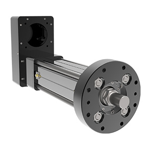
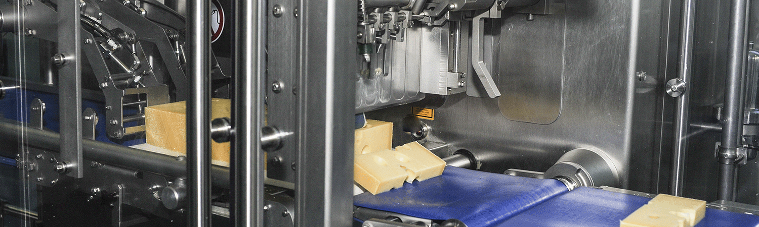
For example: If your actuator has a continuous current rating of 10 A and a continuous force rating of 1000 lbf, this means it will take about 10 A to produce 1000 lbf of force, or 5 A to produce 500 lbf of force, and so on. What if you need to push more than 1000 lbf? In most cases, you would look at a stronger stator or a larger actuator. What if it’s only for a few seconds? Could you over-work the current actuator? Well the answer is yes, and calculating by how much isn’t too difficult.

Let’s say you need to push 1500 lbf. This would be equivalent to 1.5x the continuous current rating of 10 A. If you look below, the graph recommends no more than a 22% duty cycle in this case. This means you can run the actuator 22% of the time at 15 A without overheating. The other 78% of the time, it needs to be off/cooling.

How long can you run at peak current?

Not a simple question, nor a simple answer. In reality, so many things affect this (how the system is built and how well the actuator is able to dissipate heat, are there additional heat sinks, particles in the air, degree of vacuum, new starting temp each time? (i.e. doesn’t always start from cold, etc.). Therefore, accurate times and temperature are quite difficult to estimate.

For example: At peak current (2x Continuous), the allowable duty cycle is 4%. That doesn’t mean you can run for 4 hours straight as long as you have 96 hours of off time in between however. From experience, a good rule of thumb we’ve estimated is 30s to a minute of peak current run time. Try to keep it under that, and then of course allow it to cool for the other 96% of the time.

That is going to depend on the application, but with equivalent specifications and characteristics, a roller screw actuator will typically be very similar in size to (sometimes slightly larger than) a comparable hydraulic cylinder. Hydraulics are always going to have their place in the market once you get beyond 100,000 lbs. of force, but anywhere an electromechanical roller screw actuator fits the bill, size will be very similar.

We are asked about re-lubrication intervals a lot. The reality is that there is no generic interval to re-lube actuators. It depends on so many things and every application and situation is different, it is nearly impossible to accurately calculate a re-lube interval per application. So instead, we have a rough guideline table (shown below) to give users an idea on when to start checking for old contaminated grease that needs to be replaced. However, since ambient temperature, heat dissipation, speed variation, particles in the air, etc. can vary so much from application to application, this is only a guideline. The actuator should be checked more frequently around the period this table suggests and once it is noticed that the grease is ready to be replaced (Dirty, contaminated / very dark, filled with particles / debris) – a re-lube interval can be determined.

Remember, grease needs to be cleaned out and replaced – don’t just insert more. (Except for FTX’s, those can handle 5-6 greasings before they need to be cleaned out)

RMS ROTATIONAL SPEED (RPM) RECOMMENDED GREASE RENEWAL PERIOD (HOURS)
250 10,000
500 10,000
1000 8000
1500 7000
2000 5800
2500 5000
3000 4000

Electric actuators offer high speed and force, are flexible and easily programmable for a variety of load conditions, have high accuracy and repeatability, are efficient, simple to install, require little maintenance, and are environmentally friendly.

By not using a hydraulic system, the user can eliminate oil leaks, reduce pollution, and improve worker safety. Electric actuators are also a non-toxic solution, especially in the food industry

A very common question for us. For the actuator itself, that is easy. There is a mechanical lead accuracy of the screw, which is usually 0.001 in/ft, a typical specification for precision positioning screws of any type. This means that at any point over the cumulative length of the screw, the lead will vary by a maximum of 0.001 inches per foot of screw length. This is not the same as mechanical repeatability. The mechanical repeatability is a tolerance on how close to the same linear position the screw will return, if approaching from the same direction, and driven exactly the same number of turns. This value is approximately 0.0004 inches.

The electronic positioning resolution is a function of the feedback device and the servo amplifier. Let’s assume that we have Exlar’s standard encoder on a GSX30 with 0.2 inches per revolution lead on the roller screw. Exlar’s standard encoder has 2048 lines and 8192 electronic pulses per revolution that it outputs to the servo drive. So in a perfect world, the positioning resolution would be (0.2 in/rev)/ (8192 pulses/rev) or 0.0000244 inches. Anyone who has used servo drives knows that you can’t position to one encoder pulse. Let’s use 10 encoder pulses as a reasonable best positioning capability. This gives us a positioning resolution of 0.000244 inches.

More things to consider: When addressing repeatability and accuracy, several things must also be taken into account. One of these is the stiffness of the system. Stiffness is how much the system will stretch or compress under compressive or tensile forces. If the combination of the stiffness of the actuator and the stiffness of the mechanical system, including all couplings, mounting surface, etc. allows for more compression or stretch than the required positioning resolution of the system, obtaining acceptable positioning results will be nearly impossible. Another consideration is thermal expansion and contraction. Consider a GS actuator attached to a tool that is doing a precision grinding process. Assuming that the tool is steel and 12 inches long, a 5 degree rise in temperature will cause the tool to expand by 0.0006 inches. If the system is programmed to make 0.0002 inch moves, this expansion could cause serious positioning problems. The same applies to the components of the actuator itself. The actuator rod can change in temperature from a cold start up to running temperature. This change may need to be accounted for in very precise positioning applications.

The maintenance schedule for any geared mechanical device, whether ball screw, roller screw, or gearhead, is going to be based on the amount of heat that is generated in the application, the amount of degradation of the grease, the type of grease being used, and the duty cycle. We provide some guidelines for our customers as starting points, but we recommend that for all new installations the lubrication be periodically inspected for presence and degradation as the best method for determining the right maintenance schedule for a given application. Having said that, we’ve seen repairs of units that have been in use for 15 years and when we’ve asked about grease renewal, they didn’t even realize that the unit could be serviced in the field. So we’ve had situations like that where they’ve gone for long periods of time with effectively no maintenance or no grease renewal. There are other applications that require grease renewal in very short intervals just due to the nature of the application.

On a conventional roller screw design package, there typically is an anti-rotation groove designed into the housing, and a tab designed into the nut that rides in the housing groove as the actuator extends and retracts. In regards to the inverted roller screw design, part of the installation or the application requirement is going to be having that shaft solidly mounted a machine coupling or tooling on the machine otherwise providing some sort of external anti-rotation device on that output shaft. There are other ways of using splines and different types of non-circular output shafts that can allow for different types of spline nuts that will provide anti-rotation, but typically you’re going to see that mounted on the machine.

The L10 expected life of a roller screw linear actuator is expressed as the linear travel distance that 90% of properly maintained roller screws manufactured are expected to meet or exceed. This calculation should be used for estimation purposes only.

The underlying formula that defines this value is: Travel life in millions of inches, where:
Ca= Dynamic load rating (lbf)
Fcml= Cubic mean applied load (lbf)
ℓ = Roller screw lead (inches)

For additional details on calculating estimated service life, please refer www.cw-actuation.com.

L10=(Ca)3 x ℓ Fcm

Models and Drawings

Pre-sale drawings and models are representative and are subject to change. Please consult your local Exlar representative for additional details.


Model & Quote Builder

Add items using the button below, once you’ve clicked ‘Add Item’ wait for the pop up to load. Once loaded you can select a product, configure it, download the model drawings and add it to the quote builder. You can then fill in your details and submit this request to us.

Item Summary Qty Remove


Please add one or more model masks before confirming quote

Request quote

print