
Exlar Products
Universal Linear Actuators
Integrated Motor | Actuators
Intelligent Drive | Motor | Actuators
Rotary Actuators
Exlar Legacy Product Support
Industries
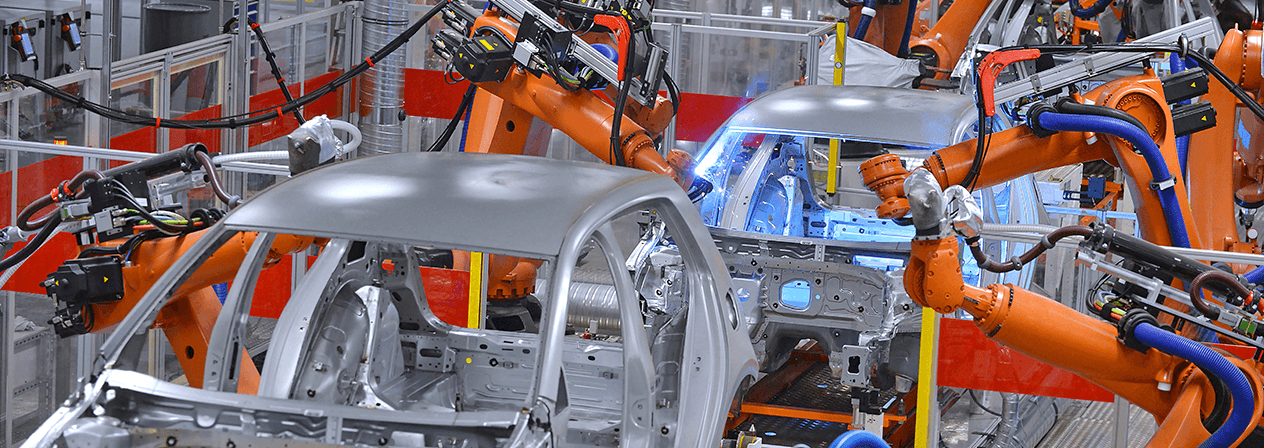
Automotive / EV Battery / Pressing
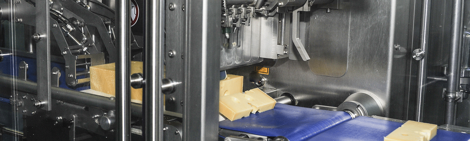
Food & Beverage / Packaging
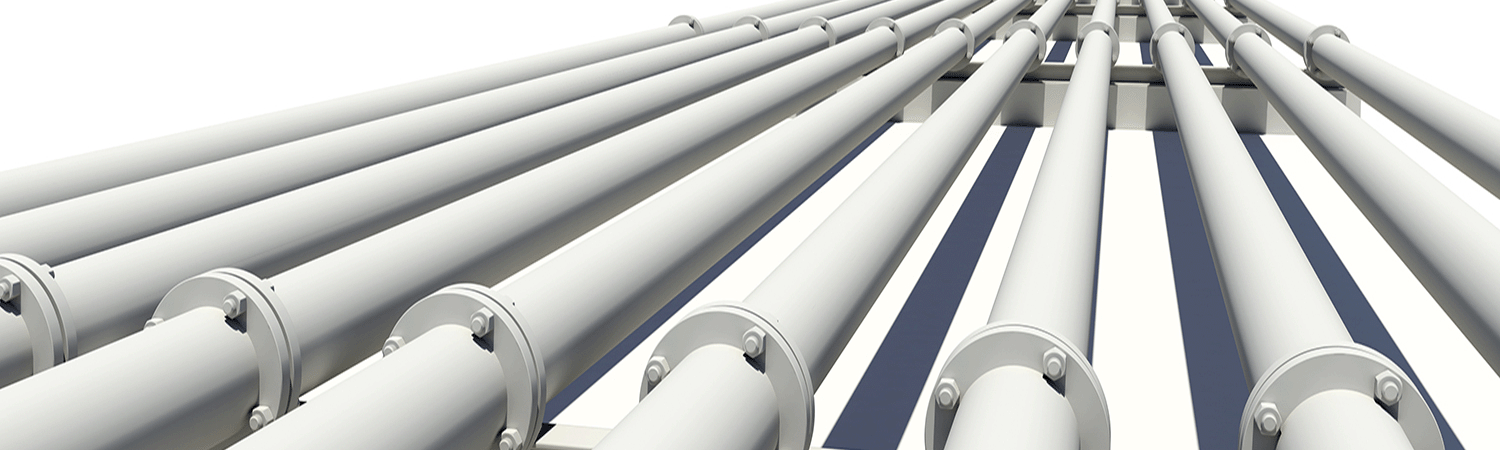
Oil & Gas
Plastics
Forestry
Entertainment / Simulation
Other Industries


.jpg "FTP-Time-Life-Estiamte-(1).jpg")


