

Industrial - Exlar
| 型 | 框架尺寸(毫米) | 中风(英寸) | 最大连续力磅 (kN) | 最大速度(毫米/秒) |
| FT35 | 3.5 (90) | 6, 12, 18, 24, 36, 48 | 5,000 (22.2) | 59.3 (1506) |
| FT45 | 4.7 (120) | 6, 12, 18, 24, 36, 48 | 10,000 (44.5) | 23 (584) |
| FT60 | 5.9 (150) | 12, 24, 36, 48 | 20,000 (89.0) | 39 (991) |
| FT80 | 7.9 (200) | 12, 24, 36, 48 | 40,000 (177.9) | 34.4 (874) |
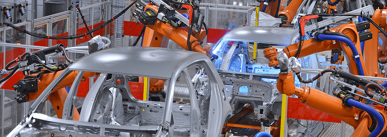
Exlar® 的 FT 系列执行器使用安装在挤压铝制外壳内的行星滚柱丝杠。 这些电动线性执行器与各种标准电机兼容。 电机安装和齿轮配置可满足各种应用的要求。 标准产品提供四种框架尺寸,标准行程长度可达36英寸(914 mm),额定载荷可达40,000 lbf(177 kN)。
与所有 Exlar 滚柱丝杠执行器一样,与 acme 和滚珠丝杠解决方案相比,FT 系列具有高负载能力、高速度和超长的使用寿命。 在同等尺寸下,在中等到重负载下,您可以期望 FT 系列的工作寿命是其他解决方案的 15 倍。 更大的功率,出色的耐用性和更小的占地面积使FT系列成为液压系统的卓越电动替代品。
其他优势
| 型号: | FT35, FT45, FT60, FT80 |
| 框架尺寸: | 3.5, 4.8, 6.0, 8.0英寸(90, 120, 150, 200毫米) |
| 行程长度: | 6, 12, 18, 24, 36, 48英寸(150, 300, 450, 600, 900, 1200毫米) |
| 线性速度: | 高达60英寸/秒(1524毫米/秒) |
| 最大力: | 高达40,000磅力(178千牛) |
| 标准/额定值: | IP65S |
 | |
AA = FT Frame Size | E = Motor Mounting Configurations3 |
笔记 :
1. 安装面尺寸、轴长和特定电机的其他细节可能需要特殊的适配器或安装规定。 始终与您当地的销售代表讨论您的电机选择。
2. 有关扩展温度操作,请咨询工厂以获取型号。
3. 最大标准 电机尺寸: FT35: 5.6 英寸/165 毫米,FT45: 7.1 英寸/215 毫米, FT60: 7.9 英寸/215 毫米, FT80: 8.5 英寸/300 毫米 对于超大尺寸电机,请联系您当地的销售代表。
4. 不适用于直列式电机安装座,请联系您当地的销售代表。
5. 申请详细信息必须经过批准才能与FT80一起使用。
6. 不提供 IP65 环境密封选项。
*某些选项并非在每个配置中都可用。 对于上面未列出的选项或特价,请联系您当地的 Exlar representative.
L1、L2、L3 = 可调外部行程开关(es)
外部行程开关指示到控制器的行程,并可针对原点或终端位置进行调节。
XT = 高容量滚柱丝杠
注意: XT名称用于指定几种不同的特殊旅行选项。 订购时,详细描述您需要的特定XT选项非常重要
| HIGH CAPACITY | STANDARD CAPACITY | ||||||
|---|---|---|---|---|---|---|---|
| 5 | 10 | 20 | 5 | 10 | 20 | ||
| Screw Lead | in | 0.197 | 0.394 | 0.787 | 0.197 | 0.394 | 0.787 |
| mm | 5 | 10 | 20 | 5 | 10 | 20 | |
| Maximum Force^1 | lbf | 5000 | 5000 | 5000 | 5000 | 5000 | 5000 |
| kN | 22.2 | 22.2 | 22.2 | 22.2 | 22.2 | 22.2 | |
| Estimated L_10 Life at Maximum Force | in x 10^6 | 15.4 | 24.6 | 56.7 | 8.88 | 14.15 | 32.05 |
| km | 392 | 626 | 1440 | 225.6 | 359.4 | 814.2 | |
| C_a (Dynamic Load Rating) | lbf | 21400 | 19850 | 20800 | 17800 | 16500 | 17200 |
| kN | 95.2 | 88.3 | 92.5 | 79.2 | 73.4 | 76.5 | |
| Maximum Input Torque | lbf-in | 196 | 392 | 783 | 196 | 392 | 783 |
| Nm | 22.1 | 44.3 | 88.5 | 22.1 | 44.3 | 88.5 | |
| Max Rated RPM @ Input Shaft | RPM | 4500 | 4500 | 4500 | 4500 | 4500 | 4500 |
| Maximum Linear Speed @ RPM Maximum Rated | in/sec | 14.7 | 29.5 | 59.3 | 14.7 | 29.5 | 59.3 |
| mm/sec | 373 | 750 | 1500 | 373 | 750 | 1500 | |
| 5 MM LEAD | 10 MM LEAD | 20 MM LEAD | ||
|---|---|---|---|---|
| NMT Unit - J (0) | 0.0004087 | 0.0004121 | 0.0004259 | kg-m² (at input shaft) kg-m²/inch of stroke |
| NMT Unit - J (Stroke) | 0.0000159 | 0.0000162 | 0.0000171 | kg-m² (at input shaft) kg-m²/inch of stroke |
| Inline w/ Coupler - J (0) | 0.0005127 | 0.0005161 | 0.0005299 | kg-m² (at motor shaft) kg-m²/inch of stroke |
| Inline w/ Coupler - J (Stroke) | 0.0000159 | 0.0000162 | 0.0000171 | kg-m² (at motor shaft) kg-m²/inch of stroke |
| Parallel 1:1 - J (0) | 0.0011042 | 0.0011855 | 0.001448 | kg-m² (at motor shaft) kg-m²/inch of stroke |
| Parallel 1:1 - J (Stroke) | 0.0000159 | 0.0000162 | 0.0000171 | kg-m² (at motor shaft) kg-m²/inch of stroke |
| Parallel 2:1 - J (0) | 0.0014029 | 0.0014038 | 0.0015345 | kg-m² (at motor shaft) kg-m²/inch of stroke |
| Parallel 2:1 - J (Stroke) | 0.0000040 | 0.0000040 | 0.0000043 | kg-m² (at motor shaft) kg-m²/inch of stroke |
| Standard Inline Coupling Inertia | 0.000104 kg-m² (0.000920 lbf-in s²) | |||
| BASE ACTUATOR WEIGHT | LB | KG |
|---|---|---|
| 6 Inch Stroke Length | 30 | 14 |
| 12 Inch Stroke Length | 35 | 16 |
| 18 Inch Stroke Length | 40 | 18 |
| 24 Inch Stroke Length | 45 | 21 |
| 36 Inch Stroke Length | 55 | 25 |
| 48 Inch Stroke Length | 65 | 30 |
| Adder for Inline (excluding motor) | 8 | 3.6 |
| Adder for Parallel Drive (excluding motor) | 16 | 7.3 |
| Adder for Front Flange | 5.4 | 2.5 |
| Adder for Rear Flange | 7.4 | 3.4 |
| Adder for Rear Clevis | 3 | 1.4 |
| Adder for Rear Eye | NA | NA |
| Adder for Front/Rear Angle Mounts | NA | NA |
| Adder for Two Trunnions | 19.5 | 8.9 |
| Adder for Two Foot Mounts | 3.3 | 1.5 |
| HIGH CAPACITY | STANDARD CAPACITY | ||||
|---|---|---|---|---|---|
| 5 | 10 | 5 | 10 | ||
| Screw Lead | in | 0.197 | 0.394 | 0.197 | 0.394 |
| mm | 5 | 10 | 5 | 10 | |
| Maximum Force* | lbf | 10000 | 10000 | 10000 | 10000 |
| kN | 44.5 | 44.5 | 44.5 | 44.5 | |
| Estimated L_10 Life at Maximum Force | in x 10^6 | 9.81 | 19.14 | 5.67 | 11.06 |
| km | 249.2 | 486.3 | 144 | 280.9 | |
| C_a (Dynamic Load Rating) | lbf | 36800 | 36500 | 30650 | 30400 |
| kN | 163.7 | 162.4 | 136.3 | 135.2 | |
| Maximum Input Torque | lbf-in | 392 | 783 | 392 | 783 |
| Nm | 44.1 | 88.2 | 44.1 | 88.2 | |
| Max Rated RPM @ Input Shaft | RPM | 3500 | 3500 | 3500 | 3500 |
| Maximum Linear Speed @ Maximum Rated RPM | in/sec | 11.5 | 23 | 11.5 | 23 |
| mm/sec | 292 | 583 | 292 | 583 | |
*Maximum allowable actuator-generated force that can be applied routinely. Exceeding this force may result in permanent damage to the actuator. For high force, short stroke applications, consult factory.
| 5 MM LEAD | 10 MM LEAD | ||
|---|---|---|---|
| NMT Unit - J (0) | 0.002463 | 0.002474 | kg-m² (at input shaft) kg-m²/inch of stroke |
| NMT Unit - J (Stroke) | 0.000045 | 0.000046 | kg-m² (at input shaft) kg-m²/inch of stroke |
| Inline w/ Coupler - J (0) | 0.002571 | 0.002581 | kg-m² (at motor shaft) kg-m²/inch of stroke |
| Inline w/ Coupler - J (Stroke) | 0.000045 | 0.000046 | kg-m² (at motor shaft) kg-m²/inch of stroke |
| Parallel 1:1 - J (0) | 0.006911 | 0.006921 | kg-m² (at motor shaft) kg-m²/inch of stroke |
| Parallel 1:1 - J (Stroke) | 0.000045 | 0.000046 | kg-m² (at motor shaft) kg-m²/inch of stroke |
| Parallel 2:1 - J (0) | 0.003466 | 0.003469 | kg-m² (at motor shaft) kg-m²/inch of stroke |
| Parallel 2:1 - J (Stroke) | 0.000011 | 0.000011 | kg-m² (at motor shaft) kg-m²/inch of stroke |
| Standard Inline Coupling Inertia | 0.00010743 kg-m² (0.000951 lbf-in s²) | ||
*Pulleys for parallel mount match actuator max performance ratings. Pulley inertias reflected at motor including typical pulleys, belt and standard bushings. Because of differences in belt and pulley selection due to particular motor choices, please contact your local sales representative if these values are critical to your application.
| BASE ACTUATOR WEIGHT | LB | KG |
|---|---|---|
| 6 Inch Stroke Length | 57 | 26 |
| 12 Inch Stroke Length | 68 | 31 |
| 18 Inch Stroke Length | 79 | 36 |
| 24 Inch Stroke Length | 90 | 41 |
| 36 Inch Stroke Length | 112 | 51 |
| 48 Inch Stroke Length | 135 | 61 |
| Adder for Inline (excluding motor) | 7.1 | 3.2 |
| Adder for Parallel Drive (excluding motor) | 42.5 | 19.3 |
| Adder for Front Flange | 6.1 | 2.8 |
| Adder for Rear Flange | 17.4 | 7.9 |
| Adder for Rear Clevis | 18.9 | 8.6 |
| Adder for Rear Eye | 19.8 | 9 |
| Adder for Front/Rear Angle Mounts | NA | NA |
| Adder for Two Trunnions | 17.2 | 7.8 |
| Adder for Two Foot Mounts | 10.4 | 4.7 |
| HIGH CAPACITY | STANDARD CAPACITY | ||||||
|---|---|---|---|---|---|---|---|
| 6 | 12 | 30 | 6 | 12 | 30 | ||
| Screw Lead | in | 0.236 | 0.472 | 1.181 | 0.236 | 0.472 | 1.181 |
| mm | 6 | 12 | 30 | 6 | 12 | 30 | |
| Maximum Force ^1 | lbf | 20000 | 20000 | 20000 | 20000 | 20000 | 20000 |
| kN | 89 | 89 | 89 | 89 | 89 | 89 | |
| Estimated L_10 Life at Maximum Force | in x 10^6 | 5.7 | 7.3 | 38.6 | 4.1 | 5.2 | 10.7 |
| km | 145.8 | 184.7 | 981.1 | 104.8 | 133.1 | 271.9 | |
| C_a (Dynamic Load Rating) | lbf | 57933 | 49750 | 63958 | 51900 | 44600 | 41700 |
| kN | 257.7 | 221.3 | 284.5 | 230.9 | 198.4 | 185.5 | |
| Maximum Input Torque | lbf-in | 940 | 1880 | 4699 | 940 | 1880 | 4699 |
| Nm | 106 | 212 | 531 | 106 | 212 | 531 | |
| Max Rated RPM @ Input Shaft | RPM | 2000 | 2000 | 2000 | 2000 | 2000 | 2000 |
| Maximum Linear Speed @ Maximum Rated RPM | in/sec | 7.9 | 15.8 | 39 | 7.9 | 15.8 | 39 |
| mm/sec | 201 | 401 | 1000 | 201 | 401 | 1000 | |
1 -Maximum allowable actuator-generated force that can be applied routinely. Exceeding this force may result in permanent damage to the actuator. For high force, short stroke applications, consult factory.
| 6 MM LEAD | 12 MM LEAD | 30 MM LEAD | ||
|---|---|---|---|---|
| NMT Unit - J (0) | 0.0078464 | 0.0078709 | 0.0080424 | kg-m² (at input shaft) kg-m²/inch of stroke |
| NMT Unit - J (Stroke) | 0.0002539 | 0.0002547 | 0.00026 | kg-m² (at input shaft) kg-m²/inch of stroke |
| Inline w/ Coupler - J (0) | 0.0081764 | 0.0082009 | 0.0083724 | kg-m² (at motor shaft) kg-m²/inch of stroke |
| Inline w/ Coupler - J (Stroke) | 0.0002539 | 0.0002547 | 0.00026 | kg-m² (at motor shaft) kg-m²/inch of stroke |
| Parallel 1:1 - J (0) | 0.0129357 | 0.0146113 | 0.0312682 | kg-m² (at motor shaft) kg-m²/inch of stroke |
| Parallel 1:1 - J (Stroke) | 0.0002539 | 0.0002547 | 0.00026 | kg-m² (at motor shaft) kg-m²/inch of stroke |
| Parallel 2:1 - J (0) | 0.0049158 | 0.0057202 | 0.0214777 | kg-m² (at motor shaft) kg-m²/inch of stroke |
| Parallel 2:1 - J (Stroke) | 0.0000635 | 0.0000637 | 0.0000650 | kg-m² (at motor shaft) kg-m²/inch of stroke |
| Standard Inline Coupling Inertia | 0.000330 kg-m² (0.002921 lbf-in s²) | |||
*Pulleys for parallel mount match actuator max performance ratings. Pulley inertias reflected at motor including typical pulleys, belt and standard bushings. Because of differences in belt and pulley selection due to particular motor choices, please contact your local sales representative if these values are critical to your application.
| BASE ACTUATOR WEIGHT | LB | KG |
|---|---|---|
| 12 inch Stroke Length | 100 | 45 |
| 24 inch Stroke Length | 130 | 59 |
| 36 Inch Stroke Length | 160 | 72 |
| 48 Inch Stroke Length | 190 | 86 |
| Adder for Inline (excluding motor) | 20.4 | 9.3 |
| Adder for Parallel Drive (excluding motor) | 39.1 | 17.7 |
| Adder for Front Flange | 13.4 | 6.1 |
| Adder for Rear Flange | 15.9 | 7.2 |
| Adder for Rear Clevis | 11.1 | 5 |
| Adder for Rear Eye | NA | NA |
| Adder for Front/Rear Angle Mounts | NA | NA |
| Adder for Two Trunnions | 44.3 | 20.1 |
| Adder for Two Foot Mounts | 10.4 | 4.7 |
| HIGH CAPACITY | STANDARD CAPACITY | ||||||
|---|---|---|---|---|---|---|---|
| 6 | 12 | 30 | 6 | 12 | 30 | ||
| Screw Lead | in | 0.236 | 0.472 | 1.181 | 0.236 | 0.472 | 1.181 |
| mm | 6 | 12 | 30 | 6 | 12 | 30 | |
| Maximum Force^1 | lbf | 40000 | 40000 | 40000 | 40000 | 40000 | 40000 |
| kN | 177.9 | 177.9 | 177.9 | 177.9 | 177.9 | 177.9 | |
| Estimated L_10 Life at Maximum Force | in x 10^6 | 3.1 | 4.4 | 16.3 | 1.94 | 2.55 | 5 |
| km | 78.7 | 111.4 | 414.3 | 49.3 | 64.9 | 127 | |
| C_a (Dynamic Load Rating) | lbf | 94330 | 84079 | 95971 | 80700 | 70200 | 64700 |
| kN | 419.6 | 374 | 426.9 | 359 | 312.2 | 287.8 | |
| Maximum Input Torque | lbf-in | 1880 | 3760 | 9399 | 1880 | 3760 | 9399 |
| Nm | 212 | 425 | 1062 | 212 | 425 | 1062 | |
| Max Rated RPM @ Input Shaft | RPM | 1750 | 1750 | 1750 | 1750 | 1750 | 1750 |
| Maximum Linear Speed @ Maximum Rated RPM | in/sec | 6.9 | 13.8 | 34.4 | 6.9 | 13.8 | 34.4 |
| mm/sec | 175 | 351 | 875 | 175 | 351 | 875 | |
1- Maximum allowable actuator-generated force that can be applied routinely. Exceeding this force may result in permanent damage to the actuator. For high force, short stroke applications, consult factory.
| 6 MM LEAD | 12 MM LEAD | 30 MM LEAD | ||
|---|---|---|---|---|
| NMT Unit - J (0) | 0.0302504 | 0.0303275 | 0.0308673 | kg-m² (at input shaft) kg-m²/inch of stroke |
| NMT Unit - J (Stroke) | 0.0008022 | 0.0008035 | 0.0008124 | kg-m² (at input shaft) kg-m²/inch of stroke |
| Inline w/ Coupler - J (0) | 0.0314604 | 0.0315375 | 0.0320773 | kg-m² (at motor shaft) kg-m²/inch of stroke |
| Inline w/ Coupler - J (Stroke) | 0.0008022 | 0.0008035 | 0.0008124 | kg-m² (at motor shaft) kg-m²/inch of stroke |
| Parallel 1:1 - J (0) | 0.0721056 | 0.0535533 | 0.1342578 | kg-m² (at motor shaft) kg-m²/inch of stroke |
| Parallel 1:1 - J (Stroke) | 0.0008022 | 0.0008035 | 0.0008124 | kg-m² (at motor shaft) kg-m²/inch of stroke |
| Parallel 2:1 - J (0) | 0.0198765 | 0.027049 | 0.0753395 | kg-m² (at motor shaft) kg-m²/inch of stroke |
| Parallel 2:1 - J (Stroke) | 0.0002006 | 0.0002009 | 0.0002031 | kg-m² (at motor shaft) kg-m²/inch of stroke |
| Standard Inline Coupling Inertia | 0.0001210 kg-m² (0.010709 lbf-in s²) | |||
*Pulleys for parallel mount match actuator max performance ratings. Pulley inertias reflected at motor including typical pulleys, belt and standard bushings. Because of differences in belt and pulley selection due to particular motor choices, please contact your local sales representative if these values are critical to your application.
| BASE ACTUATOR WEIGHT | LB | KG |
|---|---|---|
| 12 Inch Stroke Length | 190 | 86 |
| 24 Inch Stroke Length | 265 | 120 |
| 36 Inch Stroke Length | 340 | 153 |
| 48 Inch Stroke Length | 415 | 187 |
| Adder for Inline (excluding motor) | 54.9 | 24.9 |
| Adder for Parallel Drive (excluding motor) | 79.1 | 35.9 |
| Adder for Front Flange | 28.5 | 17.5 |
| Adder for Rear Flange | NA | NA |
| Adder for Rear Clevis | NA | NA |
| Adder for Rear Eye | NA | NA |
| Adder for Front/Rear Angle Mounts | NA | NA |
| Adder for Two Trunnions | NA | NA |
| Adder for Two Foot Mounts | 34.8 | 15.8 |

以下是给定输入电流占比连续额定电流百分比时,您的应用的最大允许占空比:
例如: 如果您的执行器的连续额定电流为 10 A,连续额定力为 1000 lbf,则意味着产生 1000 lbf 的力需要大约 10 A,产生 500 lbf 的力需要 5 A,依此类推。 如果您需要推动超过1000磅的重量怎么办? 在大多数情况下,您会考虑更强的定子或更大的致动器。 如果只有几秒钟呢? 您是否会过度使用当前的执行器? 答案是肯定的,计算多少并不难。
假设您需要推动1500 lbf。 这相当于10 A连续额定电流的1.5倍。 如果您看下面,图表建议在这种情况下占空比不超过22%。 这意味着您可以在15 A电流下运行执行器22%的时间而不会过热。 另外78%的时间,它需要关闭/冷却。

在峰值电流下可以运行多长时间?
不是一个简单的问题,也不是一个简单的答案。 实际上,影响这一点的因素有很多(系统是如何构建的,执行器散热的能力如何,是否有额外的散热器,空气中的颗粒,真空度,每次新的启动温度? (即并不总是从冷开始等)。 因此,精确的时间和温度很难估计。
例如: 在峰值电流(2x连续)时,允许的占空比为4%。 这并不意味着只要您有96个小时的休息时间,您就可以连续跑步4小时。 根据经验,我们估计的一个很好的经验法则是峰值电流运行时间为30秒到一分钟。 试着把它放在下面,然后当然让它冷却96%的时间。
我们经常被问及再润滑间隔。 现实情况是,没有通用的间隔来重新润滑执行器。 它取决于很多事情,每个应用和情况都不同,几乎不可能准确计算每个应用的再润滑间隔。 因此,我们有一个粗略的指南表(如下所示),让用户了解何时开始检查需要更换的旧污染润滑脂。 但是,由于环境温度,散热,速度变化,空气中的颗粒等可能因应用而异,因此这只是一个指南。 在此表建议的时间段内,应更频繁地检查致动器,一旦注意到润滑脂已准备好更换(脏污,污染/非常暗,充满颗粒/碎屑), 就可以确定重新润滑间隔。
请记住,润滑脂需要清理和更换 - 不要只是插入更多。 (除了FTX,在需要清理之前,它们可以处理5-6个润滑)
| 均方根转速 (转速) | 建议的润滑脂更新期(小时) |
|---|---|
| 250 | 10,000 |
| 500 | 10,000 |
| 1000 | 8000 |
| 1500 | 7000 |
| 2000 | 5800 |
| 2500 | 5000 |
| 3000 | 4000 |
对我们来说,这是一个非常普遍的问题。 对于执行器本身来说,这很容易。 螺钉的机械导程精度通常为0.001 in/ft,这是任何类型的精密定位螺钉的典型规格。 这意味着在螺钉累积长度的任意点上,每英尺螺钉长度的最大变化为 0.001 英寸。 这与机械可重复性不同。 机械可重复性是螺钉从同一方向接近并驱动完全相同的匝数时,螺钉返回的相同线性位置的公差。 此值约为 0.0004 英寸。
电子定位分辨率是反馈装置和伺服放大器的功能。 假设我们在GSX30上有Exlar的标准编码器,滚柱丝杠上每转引线为0.2英寸。 Exlar 的标准编码器每转有 2048 条线路和 8192 个电子脉冲,可输出到伺服驱动器。 因此,在理想情况下,定位分辨率将为(0.2英寸/转)/(8192脉冲/转)或0.0000244英寸。 任何使用过伺服驱动器的人都知道,您不能定位到一个编码器脉冲。 让我们使用10个编码器脉冲作为合理的最佳定位能力。 这为我们提供了0.000244英寸的定位分辨率。
需要考虑的更多事项: 在考虑可重复性和准确性时,还必须考虑几个因素。 其中之一是系统的刚度。 刚度是系统在压缩力或拉伸力下拉伸或压缩的程度。 如果执行器的刚度和机械系统的刚度(包括所有联轴器、安装面等)的组合允许比系统所需的定位分辨率更多的压缩或拉伸,那么获得可接受的定位结果几乎是不可能的。 另一个考虑因素是热膨胀和收缩。 考虑一个GS执行器连接到正在执行精密磨削过程的刀具上。 假设工具是钢的,长12英寸,温度升高5度将导致工具膨胀0.0006英寸。 如果系统被编程为进行0.0002英寸的移动,则这种扩展可能会导致严重的定位问题。 这同样适用于执行器本身的组件。 执行器杆的温度可以从冷启动到运行温度变化。 在非常精确的定位应用中,可能需要考虑这种变化。
Please log in or register to use our quote request tool, with this you can view and download 3D and 2D models and drawings, as well as build and submit a quote request.
If you do not have a login, please proceed to the registration page
RegisterIf you currently have an Exlar website account and would like to delete it, please contact


.jpg?lang=en-GB)


.jpg?lang=en-GB)
.jpg "FT60-Critical-Speed-(2).jpg")
.jpg "FT60-Max-Force-(1).jpg")
.jpg "FT60-Series-Life-Curves-(1).jpg")
.jpg "FT60A-Series-Life-Curves-(1).jpg")
.jpg "FT80-Critical-speed-(1).jpg")
.jpg "FT80-Max-Force-(1).jpg")
.jpg "FT80-Series-Life-Curves-(1).jpg")
.jpg "FT80A-Series-Life-Curves-(1).jpg")