GSM Series
previous
next

GSM Series

STANDARD CAPACITY ELECTRIC LINEAR ACTUATORS FOR EXCEPTIONAL RESULTS

Industrial - Exlar

THE GSM SERIES IS A LEGACY PRODUCT. NEED A COMPARABLE REPLACEMENT FOR THE GSM, TRY OUR GTX SERIES ACTUATORS.

  • Legacy Product Line - Try our GSX or GTX Series.
  • Continuous force up to 3,457 lbf (15 kN).
  • Speeds up to 37.5 in/s (952 mm/s).
  • Strokes from 3 to 18 in (75 to 450 mm).
  • Voltage ratings from 115 - 460 VRMS.
  • Compact size.
  • Class 1, Division 2 options available.
More Details

Overview

GSM Series

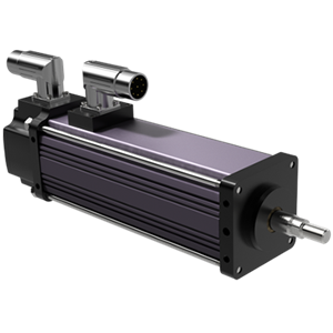
GSM Series electric linear actuators are a superior and cost effective alternative to traditional electric, hydraulic and ball screw systems. The compact design is the culmination of advanced roller screw technology and an integral brushless servo motor. This robust electric linear actuator is ideal for a variety of medium- to high-performance applications. With GSM actuators, everything from food and beverage packaging, to multi-axis turning centers, to aircraft assembly can be done cleaner, faster, and more accurately and efficiently.


More Torque and Greater Flexibility

The powerful T-LAM motor design generates 35% more torque from the same size package. These innovative actuators can be driven by almost any brand of brushless servo motor amplifier. This flexible and programmable motion control system has the capability to provide position feedback from resolvers, encoders or internally mounted sensors. It is a power dense solution that accommodates greater loads, extends travel life and minimizes maintenance. GSM by Exlar® is the new standard of excellence in standard capacity all-electric actuators.


Other Advantages

  • Integrated motor and actuator in a single compact unit
  • Designed for closed loop servo systems
  • Sealed housing for long life and minimum maintenance
  • Compatible with nearly any servo amplifier
  • Maximum slot fill for maximum motor performance
  • 100% continuous duty cycles
Quick Data
Models:
GSM20, GSM30, GSM40
Frame Sizes:
2, 3, 4 in (60, 80, 100 mm)
Stroke Length:

3, 4, 6, 8, 10, 12, 14, 18 in
(76, 102, 152, 203, 254, 305, 356, 457 mm)

Screw Lead:
0.1, 0.2, 0.4, 0.5, 0.75 in (2, 5, 10, 13, 19 mm)
Linear Speeds:
up to 37.5 in/s (952 mm/s)
Continuous Thrust Capacity:
103 to 3,457 lbf (458 to 15.3 kN)
Standards/Ratings:
UL Class 180H insulation, IP54S (IP65S op

* Some options are not available with every configuration. For options or specials not listed above or for extended temperature operation, please consult Exlar Applications Engineering.

GSM Series Configuration OptionsOpen arrow

GSM Series Configuration Options A-F

AA = GSM Actuator Size (nominal)
BB = Stroke Length
CC = Screw Lead
= Connections
= Mounting
= Rod End Thread / Rod Material


GGG = Feedback Type
Your choice of drive will dictate the appropriate feedback device for your situation. Options for feedback type include an array of absolute, analog and incremental encoders, as well as custom feedback alternatives.


HHH = Motor Stator
Motor Stator options are described with a 3-digit code. The first digit calls out the stack length, the second digit designates the rated bus voltage, and the third digit identifies the number of poles. Please refer to the mechanical/electrical specifications for motor torque and actuator rated force.

Motor Stators (all 8 Pole and Class 180H)


1A8 = 1 stack, 24 VDC *

2A8 = 2 stack, 24 VDC *

1B8 = 1 stack, 48 VDC *

2B8 = 2 stack, 48 VDC *

1C8 = 1 stack, 120 VDC *

2C8 = 2 stack, 120 VDC *

118 = 1 stack, 115 VRMS

218 = 2 stack, 115 VRMS

138 = 1 stack, 230 VRMS

238 = 2 stack, 230 VRMS

158 = 1 stack, 400 VRMS

258 = 2 stack, 400 VRMS

168 = 1 stack, 460 VRMS

268 = 2 stack, 460 VRMS


* Low voltage stators may be limited to less than catalog rated torque and/or speed. Please contact your local sales representative when ordering this option.


II = Motor Speed
All Exlar T-LAM™ motors and actuators have a standard motor speed designator (described below). The designator represents the standard base speed of the motor for the selected bus voltage.
 

Designator 

Base Speed

Actuator/Motor Series

-50

5000 rpm

GSM20

-30

3000 rpm

GSM30, GSM40

-01 … -99

 Specialized speed *


Note: It is not possible to produce every possible speed for each motor at each voltage. *

GSM Series Mechanical OptionsOpen arrow

AR = External Anti-rotate Assembly
This assembly restricts the actuator output rod from rotating when the load is not held by another method. Shorter actuators have a single anti-rotation mechanism; longer lengths have a mechanism on both sides.


L1, L2, L3 = Adjustable External Travel Switches
External travel switches indicate travel to the controller and are adjustable for either the home or end position.


RB = Rear Electric Brake
This is a rear, internal holding brake. The rear brake is spring activated and electrically released.

SR = Splined Main Rod
A ball spline shafting main rod with a ball spline nut that replaces the standard front seal and bushing assembly. This rod restricts rotation without the need for an external mechanism. The rod diameter will be the closest metric equivalent to our standard rod sizes. Since this option is NOT sealed, it is not suitable for environments in which contaminants may enter the actuator.

Note: Adding this option affects the overall length and mounting dimensions.

GSM Series Class 1, Division 2 Configuration OptionsOpen arrow

GSM Class I Division 2 Configuration Options A-J

AA = Actuator Frame Size (nominal)
BB = Stroke Length
CC = Screw Lead (position change per motor revolution)
= Connections
= Mounting
= Rod End Thread / Rod Material


GGG = Feedback Type
Your choice of drive will dictate the appropriate feedback device for your situation. Options for feedback type include an array of absolute, analog and incremental encoders, as well as custom feedback alternatives.

= Motor Stacks
= Voltage Rating
= Motor Poles


KK = Motor Speed
All Exlar T-LAM™ motors and actuators have a standard motor speed designator (described below). The designator represents the standard base speed of the motor for the selected bus voltage.

Designator

Base Speed

Actuator / Motor Series

-30

3000 rpm

GSX/M30, GSX/M40

-24

2400 rpm

GSX/M50, GSX60

-01 … -99

specialized speed *


Note: It is not possible to produce every possible speed for each motor at each voltage. *

GSM Series Class 1, Division 2 Mechanical OptionsOpen arrow

AR = External Anti-rotate Assembly
This assembly restricts the actuator output rod from rotating when the load is not held by another method. Shorter actuators have a single anti-rotation mechanism; longer lengths have a mechanism on both sides.

NI = Non-incendive Construction (required for Class I Div 2)
Construction of equipment that, under normal operating conditions, is not capable, due to arcing or thermal effects, of igniting the flammable gas-, vapor-, or dust-air mixture.


RB = Rear Electric Brake
This is a rear, internal holding brake. The rear brake is spring activated and electrically released.

GSM Series Class 1, Division 2 Special OptionsOpen arrow

GSM Class I Division 2 Special Rod End Attachments

Please note that specialized rod end attachments must be ordered separately from the actuator. 

CP = Clevis Pin
RC = Rear Clevis Pin
RE = Rod Eye
SRM = Spherical Rod Eye
 

XL = Special (Non-Standard) Lubrication
The XL option in the model number specifies some form of lubrication other than the standard provided by Exlar®, which is Mobilith SHC220. Special lubricants include other greases, such as JAX FG-2 food grade or Mobilgrease 28. Another non-standard option is oil cooling.*


XM = Special Motor Option
Special Motor Options should be listed as XM and must be approved by Exlar.*

Product Specifications

GSM20 Performance SpecificationsOpen arrow

GSM20 MECHANICAL SPECIFICATIONS

Motor Stacks


1

1

1

2

2

2

Screw Lead Designator


1

2

4

1

2

4

Screw Lead

in

0.1

0.2

0.4

0.1

0.2

0.4


mm

2.54

5.08

10.16

2.54

5.08

10.16

Continuous Force (Motor Limited)

lbf

367

195

103

578

307

163


N

1632

867

459

2571

1366

723

Max Velocity

in/sec

8.3

16.8

33.3

8.3

16.8

33.3


mm/sec

211.7

423.3

846.7

211.7

423.3

846.7

Friction Torque  (standard screw)

in-lbf

1

1

1

1.1

1.1

1.1


N-m

0.12

0.12

0.12

0.12

0.12

0.12

Friction Torque  (preloaded screw)

in-lbf

1.25

1.25

1.25

1.25

1.25

1.25


N-m

0.14

0.14

0.14

0.14

0.14

0.14

Min Stroke

in

3

3

3

3

3

3


mm

76

76

76

76

76

76

Max Stroke

in

12

12

12

12

12

12


mm

305

305

305

305

305

305

C_a (Dynamic Load Rating)

lbf

1568

1219

738

1568

1219

738


N

6970

5422

3283

6970

5422

3283

Inertia (zero stroke)

lb-in-s^2

0.0007758

0.0007758

0.0007758

0.00086

0.00086

0.00086


Kg-m^2

0.0000008766

0.0000008766

0.0000008766

0.0000009717

0.0000009717

0.0000009717

Inertia Adder  (per inch of stroke)

lb-in-s^2/in

0.00004667

0.00004667

0.00004667

0.00004667

0.00004667

0.00004667


Kg-m^2/in

0.00000005273

0.00000005273

0.00000005273

0.00000005273

0.00000005273

0.00000005273

Weight (zero stroke)

lb

4.5

4.5

4.5

5

5

5


Kg

2.04

2.04

2.04

2.27

2.27

2.27

Weight Adder (per inch of stroke)

lb

0.5

0.5

0.5

0.5

0.5

0.5


Kg

0.23

0.23

0.23

0.23

0.23

0.23

GSM20 Data CurvesOpen arrow


Test data derived using NEMA recommended aluminum heatsink 10″ x 10″ x 1/4″on GSM20.
GSM30 Performance SpecificationsOpen arrow

GSM30 MECHANICAL SPECIFICATIONS

Motor Stacks

1

1

1

2

2

2

Screw Lead Designator

1

2

5

1

2

5

Screw Lead

in

0.1

0.2

0.5

0.1

0.2

0.5


mm

2.54

5.08

12.7

2.54

5.08

12.7

Continuous Force (Motor Limited)

lbf

792

449

190

1277

724

306


N

3521

1995

845

5680

3219

1363

Max Velocity

in/sec

5

10

25

5

10

25


mm/sec

127

254

635

127

254

635

Friction Torque  (standard screw)

in-lbf

1.5

1.5

1.5

1.7

1.7

1.7


N-m

0.17

0.17

0.17

0.19

0.19

0.19

Friction Torque  (preloaded screw)

in-lbf

1.75

1.75

1.75

1.75

1.75

1.75


N-m

0.2

0.2

0.2

0.2

0.2

0.2

Min Stroke

in

3

3

3

3

3

3


mm

76

76

76

76

76

76

Max Stroke

in

18

18

18

18

18

18


mm

457

457

457

457

457

457

C_a (Dynamic Load Rating)

lbf

3310

3570

3016

3310

3570

3016


N

14724

15880

13416

14724

15880

13416

Inertia (zero stroke)

lb-in-s^2

0.002655

0.002655

0.002655

0.002829

0.002829

0.002829


Kg-m^2

0.000003000

0.000003196

Inertia Adder  (per inch of stroke)

lb-in-s^2/in

0.0001424


Kg-m^2/in

0.0000001609

Weight (zero stroke)

lb

6.5

6.5

6.5

7.65

7.65

7.65


Kg

2.95

2.95

2.95

3.47

3.47

3.47

Weight Adder (per inch of stroke)

lb

1.1

1.1

1.1

1.1

1.1

1.1


Kg

0.5

0.5

0.5

0.5

0.5

0.5


GSM30 ELECTRICAL SPECIFICATIONS

Motor Stator


118

138

158

168

218

238

258

268

Bus Voltage

Vrms

115

230

400

460

115

230

400

460

Speed @ Bus Voltage

rpm

3000

3000

3000

3000

3000

3000

3000

3000

RMS Sinusoidal Commutation

Continuous Motor Torque

lbf-in

16.9

16.8

16.3

16

26.9

27.1

26.7

27


Nm

1.91

1.9

1.84

1.81

3.04

3.06

3.01

3.05

Torque Constant  (Kt) (+/- 10% @ 25°C)

lbf-in/A

4.4

8.7

15.5

17.5

4.4

8.7

15.5

17.5


Nm/A

0.49

0.99

1.75

1.97

0.49

0.99

1.75

1.97

Continuous Current Rating

A

4.3

2.2

1.2

1

6.9

3.5

1.9

1.7

Peak Current Rating

A

8.6

4.3

2.4

2

13.8

6.9

3.8

3.4

O-PK Sinusoidal Commutation

Continuous Motor Torque

lbf-in

16.9

16.8

16.3

16

26.9

27.1

26.7

27


Nm

1.91

1.9

1.84

1.81

3.04

3.06

3.01

3.05

Torque Constant  (Kt) (+/- 10% @ 25°C)

lbf-in/A

3.1

6.2

11

12.4

3.1

6.2

11

12.4


Nm/A

0.35

0.7

1.24

1.4

0.35

0.7

1.24

1.4

Continuous Current Rating

A

6.1

3

1.7

1.4

9.7

4.9

2.7

2.4

Peak Current Rating

A

12.2

6.1

3.3

2.9

19.5

9.8

5.4

4.9

Motor Stator Data

Voltage Constant  (Ke) (+/- 10% @ 25°C)

Vrms/Krpm

29.8

59.7

105.8

119.3

29.8

59.7

105.8

119.3


Vpk/Krpm

42.2

84.4

149.7

168.7

42.2

84.4

149.7

168.7

Pole Configuration

8

8

8

8

8

8

8

8

Resistance  (L-L)(+/- 5% @ 25°C)

Ohms

2.7

10.8

36.3

47.9

1.1

4.4

14.1

17.6

Inductance (L-L)(+/- 15%)

mH

7.7

30.7

96.8

123

3.7

14.7

46.2

58.7

Brake Inertia

lbf-in-sec^2

0.00033

0.00033

0.00033

0.00033

0.00033

0.00033

0.00033

0.00033


Kg-cm^2

0.38

0.38

0.38

0.38

0.38

0.38

0.38

0.38

Brake Current @ 24 VDC

A

0.5

0.5

0.5

0.5

0.5

0.5

0.5

0.5

Brake Holding Torque

lbf-in

40

40

40

40

40

40

40

40


Nm

4.5

4.5

4.5

4.5

4.5

4.5

4.5

4.5

Brake Engage/Disengage Time

ms

19/29

19/29

19/29

19/29

19/29

19/29

19/29

19/29

Mechanical Time Constant  (tm), ms

min

4.9

4.9

5.2

5.4

2

2

2

2


max

9.4

9.5

10.1

10.5

3.9

3.8

3.9

3.8

Electrical Time Constant (te)

ms

2.9

2.8

2.7

2.6

3.3

3.4

3.3

3.3

Insulation Class

180 (H)

180 (H)

180 (H)

180 (H)

180 (H)

180 (H)

180 (H)

180 (H)


Test data derived using NEMA recommended aluminum heatsink 10" x 10" x 3/8" at 25°C Specifications subject to change without notice. 
GSM30 Data CurvesOpen arrow

Test data derived using NEMA recommended aluminum heatsink 10″ x 10″ x 3/8″ on GSM30


Test data derived using NEMA recommended aluminum heatsink 10″ x 10″ x 3/8″ on GSM30


Test data derived using NEMA recommended aluminum heatsink 10″ x 10″ x 3/8″ on GSM30
 
GSM40 Performance SpecificationsOpen arrow

GSM40 MECHANICAL SPECIFICATIONS

Motor Stacks


1

1

1

1

2

2

2

2

Screw Lead Designator

1

2

5

8

1

2

5

8

Screw Lead

in

0.1

0.2

0.5

0.75

0.1

0.2

0.5

0.75


mm

2.54

5.08

12.7

19.05

2.54

5.08

12.7

19.05

Continuous Force (Motor Limited)

lbf

2089

1194

537

358

3457

1975

889

593


N

9293

5310

2390

1593

15377

8787

3954

2636

Max Velocity

in/sec

5

10

25

37.5

5

10

25

37.5


mm/sec

127

254

635

953

127

254

635

953

Friction Torque  (standard screw)

in-lbf

2.7

2.7

2.7

2.7

3

3

3

3


N-m

0.31

0.31

0.31

0.31

0.34

0.34

0.34

0.34

Friction Torque  (preloaded screw)

in-lbf

3

3

3

3

3

3

3

3


N-m

0.34

0.34

0.34

0.34

0.34

0.34

0.34

0.34

Min Stroke

in

4

4

4

4

6

6

6

6


mm

102

102

102

102

152

152

152

152

Max Stroke

in

18

18

18

12

18

18

18

12


mm

457

457

457

305

457

457

457

305

C_a (Dynamic Load Rating)

lbf

4736

4890

4218

3328

4736

4890

4218

3328


N

21067

21751

18763

14804

21067

21751

18763

14804

Inertia (zero stroke)

lb-in-s^2

0.01132

0.01132

0.01132

0.01132

0.01232

0.01232

0.01232

0.01232


Kg-m^2

0.001279

0.001279

0.001279

0.001279

0.001392

0.001392

0.001392

0.001392

Inertia Adder  (per inch of stroke)

lb-in-s^2/in

0.000564

0.000564

0.000564

0.000564

0.000564

0.000564

0.000564

0.000564


Kg-m^2/in

0.0000006372

Weight (zero stroke)

lb

8

8

8

8

11.3

11.3

11.3

11.3


Kg

3.63

3.63

3.63

3.63

5.13

5.13

5.13

5.13

Weight Adder (per inch of stroke)

lb

2

2

2

2

2

2

2

2


Kg

0.91

0.91

0.91

0.91

0.91

0.91

0.91

0.91


GSM40 ELECTRICAL SPECIFICATIONS

Motor Stator


118

138

158

168

218

238

258

268

Bus Voltage

Vrms

115

230

400

460

115

230

400

460

Speed @ Bus Voltage

rpm

3000

3000

3000

3000

3000

3000

3000

3000

RMS Sinusoidal Commutation

Continuous Motor Torque

lbf-in

47.5

47.5

45.9

45.4

75.1

78.6

78.7

79.5


Nm

5.37

5.36

5.19

5.13

8.49

8.89

8.89

8.99

Torque Constant  (Kt) (+/- 10% @ 25°C)

lbf-in/A

4.1

8.2

14.5

16.8

4.1

8.2

14.5

16.8


Nm/A

0.46

0.93

1.64

1.9

0.46

0.93

1.64

1.9

Continuous Current Rating

A

12.9

6.5

3.5

3

20.5

10.7

6

5.3

Peak Current Rating

A

25.9

12.9

7.1

6

40.9

21.4

12.1

10.6

O-PK Sinusoidal Commutation

Continuous Motor Torque

lbf-in

47.5

47.5

45.9

45.4

75.1

78.6

78.7

79.5


Nm

5.37

5.36

5.19

5.13

8.49

8.89

8.89

8.99

Torque Constant  (Kt) (+/- 10% @ 25°C)

lbf-in/A

2.9

5.8

10.3

11.9

2.9

5.8

10.3

11.9


Nm/A

0.33

0.66

1.16

1.34

0.33

0.66

1.16

1.34

Continuous Current Rating

A

18.3

9.1

5

4.3

28.9

15.1

8.5

7.5

Peak Current Rating

A

36.6

18.3

10

8.6

57.9

30.3

17.1

15

Motor Stator Data


Voltage Constant (Ke)  (+/- 10% @ 25°C)

Vrms/Krpm

28

56

99.3

114.6

28

56

99.3

114.6


Vpk/Krpm

39.6

79.2

140.5

162.1

39.6

79.2

140.5

162.1

Pole Configuration

8

8

8

8

8

8

8

8

Resistance  (L-L)(+/- 5% @ 25°C)

Ohms

0.42

1.7

5.7

7.8

0.2

0.72

2.26

3

Inductance (L-L)(+/- 15%)

mH

3

11.9

37.5

49.9

1.2

5.4

18.2

23.1

Brake Inertia

lb-in-sec^2

0.00096

0.00096

0.00096

0.00096

0.00096

0.00096

0.00096

0.00096


Kg-cm^2

1.08

1.08

1.08

1.08

1.08

1.08

1.08

1.08

Brake Current @ 24 VDC

A

0.67

0.67

0.67

0.67

0.67

0.67

0.67

0.67

Brake Holding Torque

bf-in

97

97

97

97

97

97

97

97


Nm

11

11

11

11

11

11

11

11

Brake Engage/Disengage Time

ms

20/29

20/29

20/29

20/29

20/29

20/29

20/29

20/29

Mechanical Time Constant (tm), ms

min

4.5

4.5

4.8

4.9

2.1

1.9

1.9

1.9


max

6

6

6.4

6.6

2.8

2.6

2.6

2.5

Electrical Time Constant (te)

ms

7

7

6.6

6.4

5.9

7.5

8

7.8

Insulation Class

180 (H)

180 (H)

180 (H)

180 (H)

180 (H)

180 (H)

180 (H)

180 (H)


Test data derived using NEMA recommended aluminum heatsink 12" x 12" x 1/2" at 25°C Specifications subject to change without notice
GSM40 Data CurvesOpen arrow


Test data derived using NEMA recommended aluminum heatsink 12″ x 12″ x 1/2″ on GSM40

Test data derived using NEMA recommended aluminum heatsink 12″ x 12″ x 1/2″ on GSM40


Test data derived using NEMA recommended aluminum heatsink 12″ x 12″ x 1/2″ on GSM40


Test data derived using NEMA recommended aluminum heatsink 12″ x 12″ x 1/2″ on GSM40

Resources for GSM Series Actuators

Content Type
Industrial - Exlar, Certifications
Industrial - Exlar, Software & Downloads
Industrial - Exlar, Actuator Technical Tips
Industrial - Exlar, Brochures/Catalogs
Industrial - Exlar, Actuator Technical Tips
Siemens - ‘M’ Manufacturers Connector, Cable & Wiring Information
Industrial - Exlar, Actuator Technical Tips
Yaskawa - ‘M’ Manufacturers Connector, Cable & Wiring Information
Industrial - Exlar, Brochures/Catalogs
Hide Resources

This site uses cookies to improve our service, you can find out more here - for the best web experience please accept cookies

x