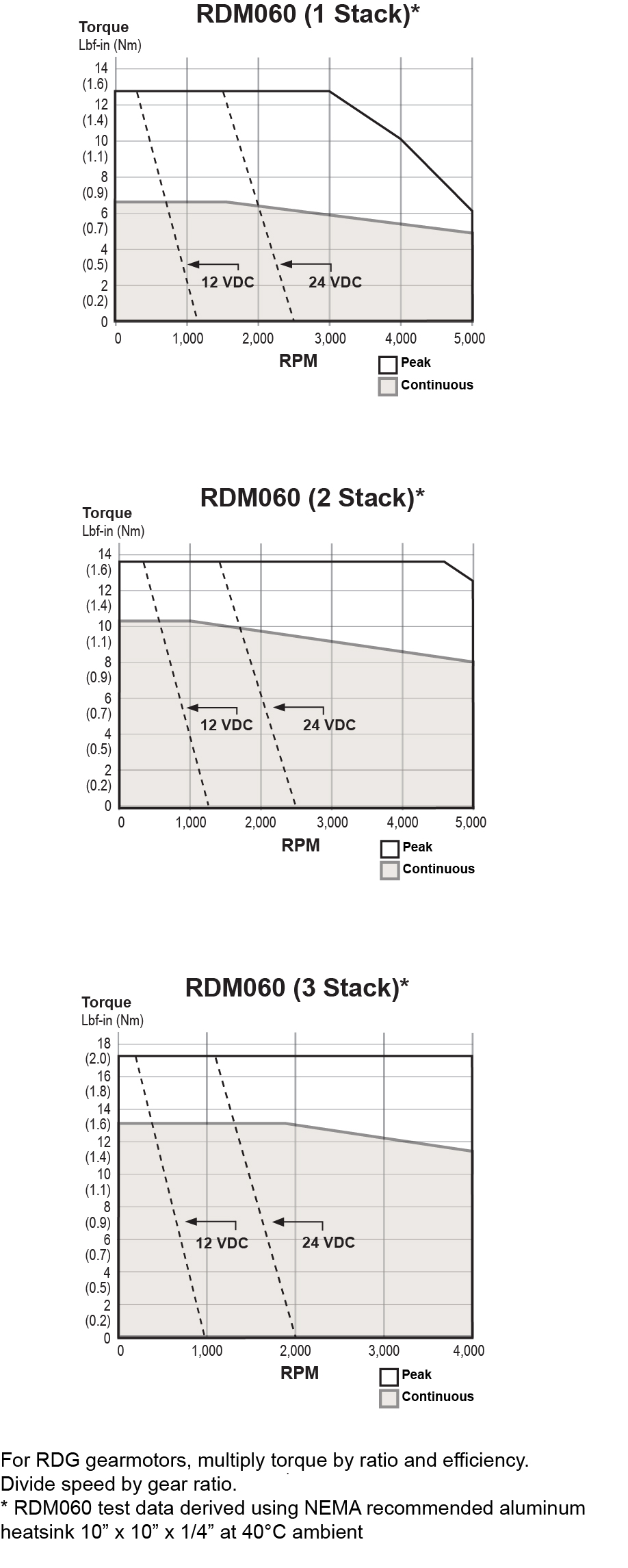
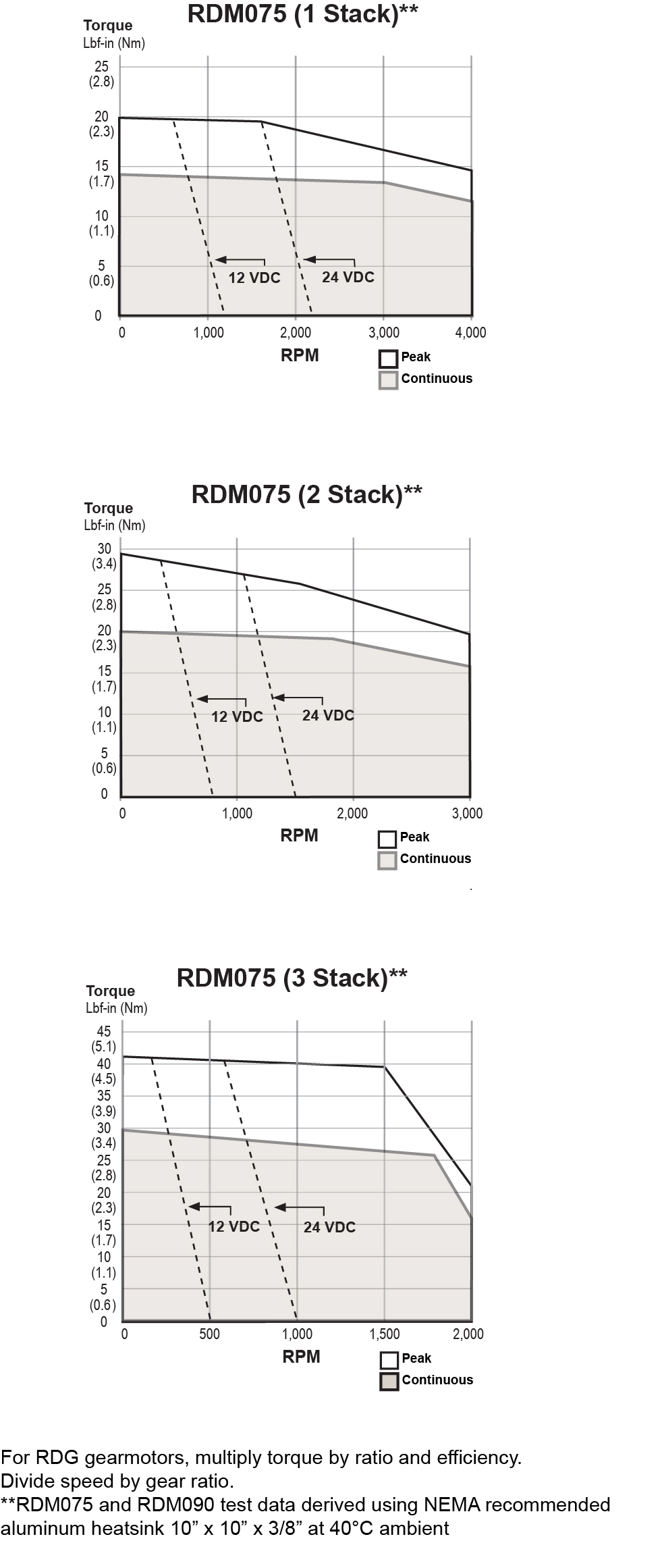
RDM/G075 Rotary Motor Torque and Speed Ratings
| |
STATOR |
1 STACK |
2 STACK |
3 STACK |
| |
rpm at 48 Vdc |
4000 |
3000 |
2000 |
| Continuous Torque |
lbf-in (Nm) |
13 (1.46) |
18.5 (2.09) |
29 (3.28) |
| Peak Torque |
lbf-in (Nm) |
18.9 (2.08) |
28 (3.16) |
41 (4.63) |
| Drive Current @ Continuous Torque |
Amps |
22 |
22 |
22 |
Operating Temperature Range**
(-40˚C available, consult Exlar) |
-20 to 65˚ C |
| Maximum Continuous Power Supply Current* |
Amps |
15 |
18 |
18 |
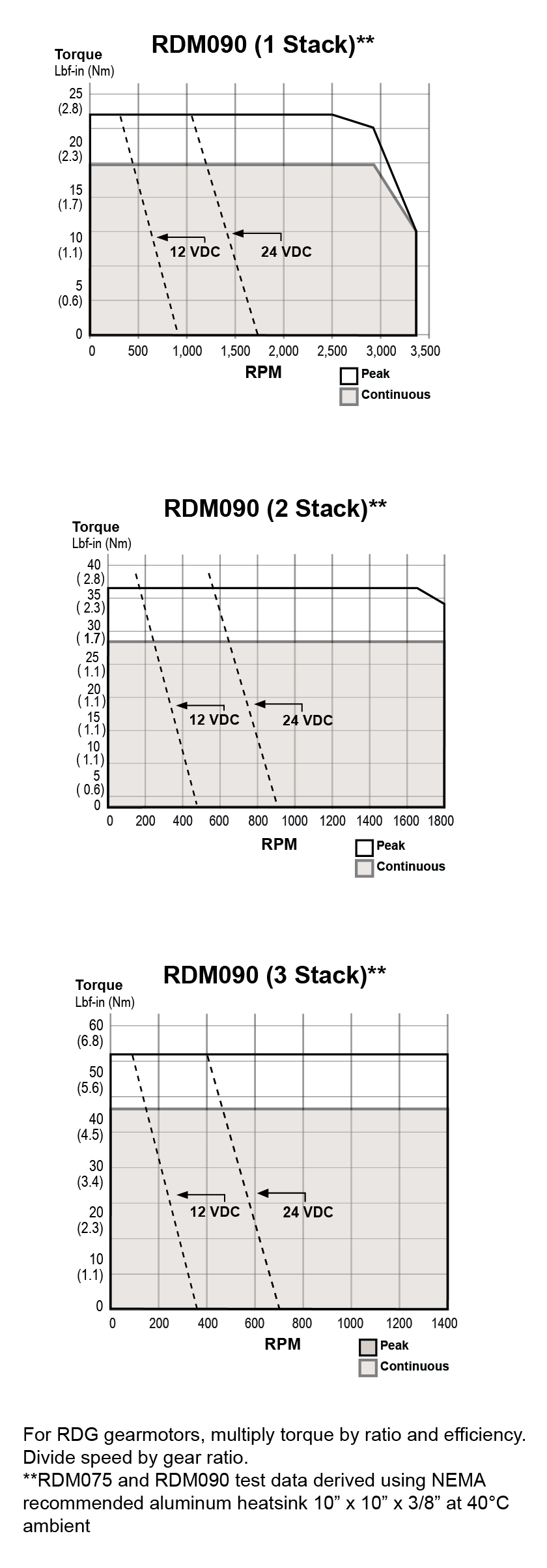
*Power supply current is based on software current limit, not thermal limit. Consideration for peak current should also be considered when sizing power supplies. For output torque of RDG gearmotors, multiply by ratio and efficiency. Please note maximum allowable output torques shown below.
**Ratings based on 40˚ C ambient conditions.
RDM/G075 Inertia
| |
STATOR |
1 STACK |
2 STACK |
3 STACK |
| RDM Motor Armature Inertia (+/-5%) |
lb-in-sec^2 (kg-cm^2) |
0.000545 (0.6158) |
0.000973 (1.0996) |
0.001401 (1.5834) |
| RDG Gearmotor Armature Inertia* (+/-5%) |
lbf-in-sec^2 (kg-cm^2) |
0.000660 (0.7450) |
0.001068 (1.2057) |
0.001494 (1.6868) |
*Add armature inertia to gearing inertia for total inertia.
RDM/G075 Radial Load and Bearing Life
| RPM |
50 |
100 |
250 |
500 |
1000 |
3000 |
| RDM075 lbf (N) |
278 (1237) |
220 (979) |
162 (721) |
129 (574) |
102 (454) |
71 (316) |
| RDG075 lbf (N) |
343 (1526) |
272 (1210) |
200 (890) |
159 (707) |
126 (560) |
88 (391) |
*Side load ratings shown above are for 10,000 hour bearing life at 25 mm from motor face at given rpm.
RDM/G075 Gearmotor Mechanical Ratings
| MODEL |
RATIO |
MAXIMUM ALLOWABLE OUTPUT
TORQUE-SET BY USER LBF-IN (NM) |
1000 RPM LBF-IN (NM) |
2500 RPM LBF-IN (NM) |
4000 RPM LBF-IN (NM) |
| RDG075-004 |
4:1 |
1618 (182.8) |
384 (43.4) |
292 (32.9) |
254 (28.7) |
| RDG075-005 |
5:1 |
1446 (163.4) |
395 (44.6) |
300 (33.9) |
260 (29.4) |
| RDG075-010 |
10:1 |
700 (79.1) |
449 (50.7) |
341 (38.5) |
296 (33.4) |
Output Torque at Motor Speed for 10,000 Hour Life. Two torque ratings for the RDG gearmotors are given in the table above. The left hand columns give the maximum (peak) allowable output torque for the indicated ratios of each size RDG gearmotor. This is not the rated output torque of the motor multiplied by the ratio of the reducer. It is possible to select a configuration of the motor selection and gear ratio such that the rated motor torque, multiplied by the gear ratio exceeds these ratings. It is the responsibility of the user to ensure that the settings of the system do not allow these values to be exceeded. The right hand columns give the output torque at the indicated speed which will result in 10,000 hour life (L10). The setup of the system will determine the actual output torque and speed.
RDM/G075 Gearing Reflected Inertia
| SINGLE REDUCTION (+/-5%) |
|
|
| Gear Stages |
lbf-in-sec^2 |
(kg-cm^2) |
| 4:1 |
0.000095 |
(0.107) |
| 5:1 |
0.000062 |
(0.069) |
| 10:1 |
0.000117 |
(0.019) |
RDM/G075 Backlash and Efficiency
| |
SINGLE REDUCTION |
| Backlash at 1% Rated Torque |
10 Arc min |
| Efficiency |
91% |
RDM/G075 Motor and Gearmotor Weights
| |
RDM075 WITHOUT GEARS |
RDG075 WITH 1 STAGE GEARING |
ADDED WEIGHT FOR BRAKE |
| 1 Stack Stator lb (kg) |
7.4 (3.4) |
9.8 (4.4) |
1.0 (0.5) |
| 2 Stack Stator lb (kg) |
9.2 (4.2) |
11.6 (5.3) |
1.0 (0.5) |
| 3 Stack Stator lb (kg) |
11 (4.9) |
13.4 (6.1) |
1.0 (0.5) |