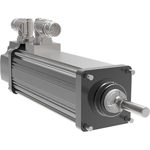
GSX Series
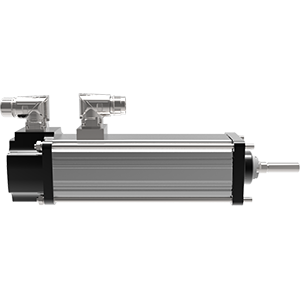
GSX Horizontal
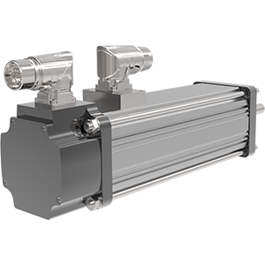
GSX Back
previous
next

GSX Series

Integrated Motor Actuator

Industrial - Exlar

  • Integrated brushless servo motor and linear rod-style actuator in one 
  • Designed for closed loop servo systems
  • Sealed housing for long life and minimum maintenance
  • Configurable for use with almost every brand of servo drive
  • Compact size
  • C1, D2 available options 
More Details

Overview

GSX Series

Quick Data
ModelFrame Size mm (in)Stroke inMax Continuous Force kN (lbf)Max Speed mm/s (in/s)
GSX2050.8 (2)
3, 6, 10, 12
2.6 (578)845.8 (33.3)
GSX3076.2 (3)
3, 6, 10, 12, 14, 18
5.7 (1,277)635 (25)
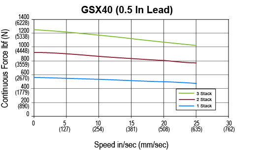
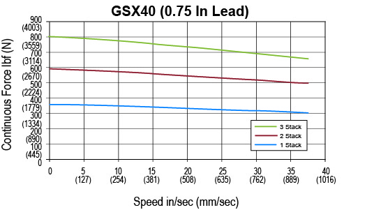
GSX40101.6 (4)
4, 6, 8, 10, 12, 18
15.4 (3,457)953 (37.5)
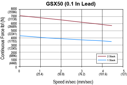
GSX50139.7 (5.5)
6, 10, 14
31.8 (7,150)1,016 (40)
GSX60177.8 (7)
6, 10
51.3 (11,528)1,016 (40)

Integrated Linear Actuator Motor Offers High Performance and Long Life

GSX Series integrated linear actuator motors integrate all the advantages of Exlar® roller screw and T-LAM stator technologies to create powerful and robust solutions with long life. The specially designed roller screw mechanism efficiently converts electric motor power into linear motion. Planetary rollers, assembled around the extending rod, follow threads that are precisely machined on the inside of the actuator’s hollow rotor.


Heavy Loads, High Speeds, Long Life

The innovative design of the GSX actuators produces smooth, accurate, and programmable linear motion that is precisely synchronized with the armature rotation. Additionally, the roller screw’s larger contact surface accommodates heavier loads at higher speeds, resulting in much longer life. The GSX compact electric linear actuator is perfect for applications that require smooth, quiet, and precise movement.

Related Industries

Quick Data
Models:GSX20, GSX30, GSX40, GSX50, GSX60
Frame Sizes:2, 3, 4, 5.5, 7 in (60, 80, 100, 140, 180 mm)
Stroke Lengths:3, 4, 6, 8, 10, 12, 14, 18 in
(76, 102, 152, 203, 254, 305, 356, 457 mm)
Screw Lead:0.1, 0.2, 0.25, 0.4, 0.5, .75, 1 in (2, 5, 6, 10, 13, 19, 25 mm)
Linear Speed:up to 37.5 in/s (952 mm/s)
Continuous Thrust Capacity:103 to 11,528 lbf (458 to 51 kN)
Standard/Rating:CE and UL Certifications, UL Class 180H insulation, IP65S
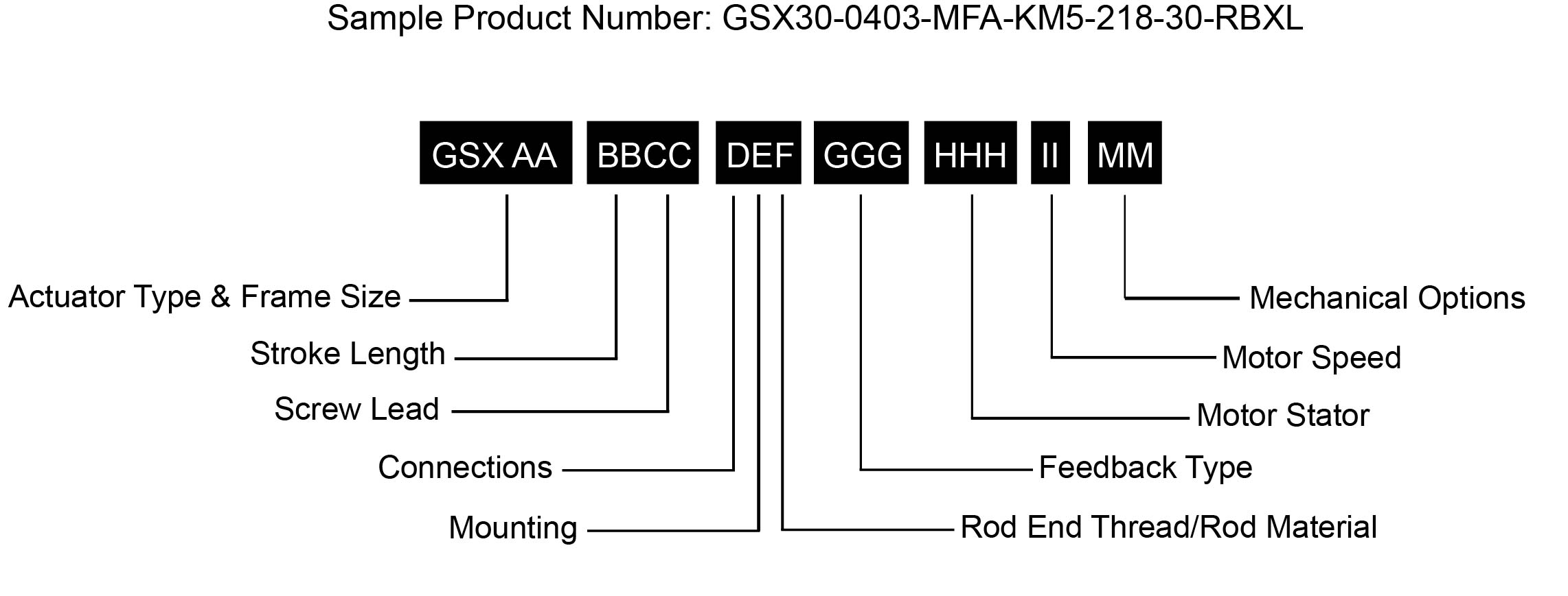
Ordering InformationArrow

GSX-Order.jpg


AA = Frame Size 
20 = 2 in (50.8 mm) 
30 = 3 in (76.2 mm) 
40 = 4 in (101.6 mm)
50 = 5.5 in (139.7 mm)
60 = 7 in (177.8 mm)

BB = Stroke Length
03 = 3 in (76 mm) GSX20, GSX30
04 = 4 in (102 mm) GSX40 
06 = 5.9 in (150 mm) GSX30; 6 in (152 mm) GSX20, GSX40, GSX50, GSX60
08 = 8 in (203 mm) GSX40
10 = 10 in (254 mm) all models
12 = 12 in (305 mm) GSX20, GSX30, GSX40
14 = 14 in (356 mm) GSX30, GSX50
18 = 18 in (457 mm) GSX30, GSX40

CC = Screw Lead
01 = 0.1 in (2.54 mm) (GSX20, GSX30, GSX40, GSX509
02 = 0.2 in (5.08 mm) (GSX20, GSX30, GSX40, GSX50)
03 = 0.25 in (6.35 mm) (GSX60)
04 = 0.4 in (10.16 mm) (GSX20 only)
05 = 0.5 in (12.7 mm) (GSX30, GSX40, GSX50, GSX60)
08 = 0.75 in (19.05 mm) (GSX40)5
10 = 1.0 in (25.4 mm) (GSX50, GSX60)6

D = Connections
I = Exlar standard M23 style7 
M = Manufacturer’s connector3

E = Mounting
C = Rear clevis
F = Front flange
R = Rear flange
D = Double side mount13
T = Side trunnion
E = Extended tie rods
K = Metric double side mount13
Q = Metric side trunnion
M = Metric extended tie rods
G = Metric rear clevis

F = Rod End Thread / Rod Material
M = Male, US standard thread
A = Male, metric thread
F = Female, US standard thread
B = Female, metric thread

GGG = Feedback Type 
See catalog for details

HHH = Motor Stator – 8 Pole 1 Class 180H12
118 = 1 stack, 115 Vrms
138 = 1 stack, 230 Vrms    
158 = 1 stack, 400 Vrms
168 = 1 stack, 460 Vrms 

218 = 2 stack, 115 Vrms    
238 = 2 stack, 230 Vrms
258 = 2 stack, 400 Vrms
268 = 2 stack, 460 Vrms
    
318 = 3 stack, 115 Vrms
338 = 3 stack, 230 Vrms    
358 = 3 stack, 400 Vrms        
368 = 3 stack, 460 Vrms
    
II = Motor Speed
24 = 2400 rpm, GSX50, GSX60            
30 = 3000 rpm, GSX30,  GSX40
50 = 5000 rpm, GSX20

MM = Mechanical Options15
AR = External anti-rotate assembly11
RB = Rear electric brake2
PB = Protective bellows10
SR = Splined main rod8, 12, 14
L1/L2/L3 = External limit switches4    


NOTES:
  1. Stator voltage and pole options allow for catalog rated performance at varying amplifier bus voltages and pole configuration requirements.      Refer to performance specification
  2. The brake option may require a third cable, consult local sales representative 
  3. Available as described in Feedback Types
  4. Requires AR option
  5. 0.75 lead not available above 12 inch
  6. 1.0 lead not available above 10 inch stroke
  7. GSX60 uses M40 size 1.5 power connector
  8. If not otherwise specified by the customer, an M24X2 male rod end will be used on the GSX50
  9. 0.1 lead not available over 10” stroke on GSX50
10. N/A with extended tie rod mounting option.
11. A second anti-rotate arm is used on GSX20, 30 and 40 for 10 inch and longer stroke
12. See optimized stator offerings in catalog
13. Anti-rotate with D or K mount N/A on 10 inch or longer stroke except in GSX50
14. Not available in Stainless Steel
15. For extended temperature operation consult factory for model number

Class 1 Division 2 Ordering InformationArrow
GSX-(H)-Order.jpg
 
AA  =  Actuator Frame Size
30 = 3 inch (76 mm)
40 = 4 inch (102 mm)
50 = 5.5 inch (140 mm)
60 = 7 inch (178 mm)

BB = Stroke Length
03 = 3 inch (76 mm) GSX30
04 = 4 inch (102mm) GSX40
06 = 5.9 inch (152 mm) GSX30 6 inch (GSX20, 40, 50, 60)
08 = 8 inch (203 mm) GSX40
10 = 10 inch (254 mm) all models
12 = 12 inch (305 mm) GSX30, 40
14 = 14 inch (356 mm) GSX30, 50
18 = 18 inch (457 mm) GSX30, 40

CC = Lead (position change per motor revolution)
01 = 0.1 inch (2.54 mm) GSX30, 40, 50
02 = 0.2 inch (5.08 mm) GSX30, 40, 50
03 = 0.25 inch (6.35 mm) GSX60
05 = 0.5 inch (12.7 mm) GSX30, 40, GSX50, 60
08 = 0.75 inch (19.05 mm) GSX401
10 = 1.0 inch (25.4 mm) GSX50, 60

D = Connections
T = Terminal box with NPT ports

E = Mounting
C = Rear clevis
F = Front flange
R = Rear flange
D = Double side mount
T = Side trunnion
E = Extended tie rods
K = Metric double side mount
Q = Metric side trunnion
M = Metric extended tie rods
G =Metric rear clevis
F = Rod End
M = Male, US std thread
A = Male, metric thread
F = Female, US std thread
B = Female, metric thread

GGG = Feedback Type
See catalog for details

H = Motor Stacks
1 = 1 stack magnets
2 = 2 stack magnets
3 = 3 stack magnets

I = Voltage Rating
A = 24 V DC
B = 48 V DC
C = 120 V DC
1 = 115 Volt RMS
3 = 230 Volt RMS
5 = 400 Volt RMS
6 = 460 Volt RMS

J = Motor Poles
8 = 8 motor poles

KK = Motor Speed
24 = 2400 rpm, GSX/M50, GSX60
30 = 3000 rpm, GSX/M30, 40

MM = Mechanical Options
NI = Non-incendive construction required for Class 1, Division 2
AR = External anti-rotate
RB = Rear electric brake
PB = Protective bellows2

NOTES:
1. 0.75 inch (19.05 mm) lead N/A over 12 inch (450 mm) stroke. 
2. Not available with extended tie rod mounting option.

* Some options are not available with every configuration. For options or specials not listed above contact your local representative. 

GSX Series Mechanical OptionsOpen arrow

AR = External Anti-rotate Assembly
This assembly restricts the actuator output rod from rotating when the load is not held by another method. Shorter actuators have a single anti-rotation mechanism; longer lengths have a mechanism on both sides.

RB = Rear Electric Brake
This is a rear, internal holding brake. The rear brake is spring activated and electrically released.

PB = Protective Bellows
An accordion-style bellows that safeguards the main actuator rod from damage due to abrasives or other contaminants in the operating environment. The bellows is made of S2 Neoprene coated nylon with sewn construction. Rated for -40 to 250 degrees F (-40 to 121 C). Not available with the extended tie rod mounting option. *

SR = Splined Main Rod
A ball spline shafting main rod with a ball spline nut that replaces the standard front seal and bushing assembly. This rod restricts rotation without the need for an external mechanism. The rod diameter will be the closest metric equivalent to our standard rod sizes. Since this option is NOT sealed, it is not suitable for environments in which contaminants may enter the actuator.

Note: Adding this option affects the overall length and mounting dimensions. Due to the reduced diameter of the splined main rod on GSX50 actuators, the standard A, F and B rod ends are not available. In this case, an “X” should be used in the rod end location. If not otherwise specified, an M24x2 male rod end will be used.

L1, L2, L3 = Adjustable External Travel Switch(es)
External travel switches indicate travel to the controller and are adjustable for either the home or end position.*

GSX Series Class 1 Division 2 Mechanical OptionsOpen arrow

NI = Non-incendive Construction (required for Class I Div 2)
Construction of equipment that, under normal operating conditions, is not capable, due to arcing or thermal effects, of igniting the flammable gas-, vapor-, or dust-air mixture.

AR = External Anti-rotate Assembly
This assembly restricts the actuator output rod from rotating when the load is not held by another method. Shorter actuators have a single anti-rotation mechanism; longer lengths have a mechanism on both sides.

RB = Rear Electric Brake
This is a rear, internal holding brake. The rear brake is spring activated and electrically released.

PB = Protective Bellows
An accordion-style bellows that safeguards the main actuator rod from damage due to abrasives or other contaminants in the operating environment. The bellows is made of S2 Neoprene coated nylon with sewn construction. Rated for -40 to 250 degrees F (-40 to 121 C). Not available with the extended tie rod mounting option. *

XM = Special Motor Option
Special Motor Options should be listed as XM and must be approved by Exlar.*

XL = Special (Non-Standard) Lubrication
The XL option in the model number specifies some form of lubrication other than the standard provided by Exlar®, which is Mobilith SHC220. Special lubricants include other greases, such as JAX FG-2 food grade or Mobilgrease 28. Another non-standard option is oil cooling.*

GSX Class I Division 2 Special Rod End Attachments
Please note that specialized rod end attachments must be ordered separately from the actuator.

CP = Clevis Pin
RC = Rear Clevis Pin
RE = Rod Eye
SRM = Spherical Rod Eye

Product Specifications

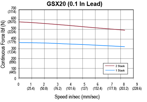
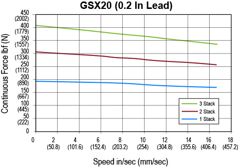
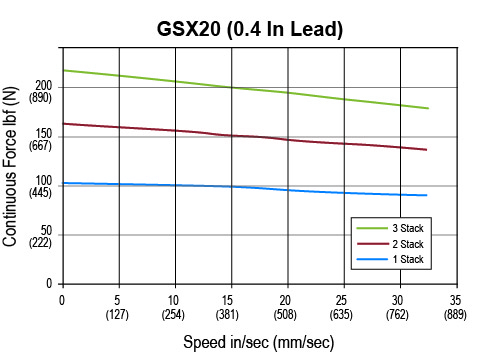
GSX20 Performance SpecificationsOpen arrow

GSX20 Performance Specifications

Motor Stacks   1 1 1 2 2 2 3 3
Screw Lead Designator   1 2 4 1 2 4 2 4
Screw Lead in 0.1 0.2 0.4 0.1 0.2 0.4 0.2 0.4
  mm 2.54 5.08 10.16 2.54 5.08 10.16 5.08 10.16
Continuous Force (Motor Limited) lbf 367 195 103 578 307 163 409 216
  N 1632 867 459 2571 1366 723 1817 962
Max Velocity in/sec 8.3 16.8 33.3 8.3 16.8 33.3 16.8 33.3
  mm/sec 211.7 423.3 846.7 211.7 423.3 846.7 423.3 846.7
Friction Torque (standard screw) in-lbf 1 1 1 1.1 1.1 1.1 1.1 1.1
  N-m 0.11 0.11 0.11 0.12 0.12 0.12 0.12 0.12
Friction Torque (preloaded screw) in-lbf 2.3 2.3 2.3 0.23 0.23 0.23 0.23 0.23
  N-m 0.25 0.25 0.25 0.26 0.26 0.26 0.26 0.26
Min Stroke in 3 3 3 3 3 3 6 6
  mm 76 76 76 76 76 76 152 152
Max Stroke in 12 12 12 12 12 12 12 12
  mm 305 305 305 305 305 305 305 305
C_a (Dynamic Load Rating) lbf 2075 1540 1230 2075 1540 1230 1540 1230
  N 9230 6850 5471 9230 6850 5471 6850 5471
Inertia (zero stroke) lb-in-s^2 0.0007758 0.0007758 0.0007758 0.0008600 0.0008600 0.0008600 0.0009442 0.0009442
  Kg-m^2 0.00008766 0.00008766 0.00008766 0.00009717 0.00009717 0.00009717 0.0001067 0.0001067
Inertia Adder (per inch of stroke) lb-in-s^2/in 0.00004667 0.00004667 0.00004667 0.00004667 0.00004667 0.00004667 0.00004667 0.00004667
  Kg-m^2/in 0.000005273 0.000005273 0.000005273 0.000005273 0.000005273 0.000005273 0.000005273 0.000005273
Weight (zero stroke) lb 4.5 4.5 4.5 5 5 5 5.5 5.5
  Kg 2.04 2.04 2.04 2.27 2.27 2.27 2.49 2.49
Weight Adder (per inch of stroke) lb 0.5 0.5 0.5 0.5 0.5 0.5 0.5 0.5
  Kg 0.23 0.23 0.23 0.23 0.23 0.23 0.23 0.23


GSX20 Electrical Specifications

Motor Stator   118 138 158 168 218 238 258 268 318* 338* 358* 368*
Bus Voltage Vrms 115 230 400 460 115 230 400 460 115 230 400 460
Speed @ Bus Voltage rpm 5000 5000 5000 5000 5000 5000 5000 5000 5000 5000 5000 5000
RMS Sinusoidal Commutation
Continuous Motor Torque lbf-in 7.6 7.3 7 7 11.9 11.5 11 11.3 15 15.3 14.6 14.9
  Nm 0.86 0.83 0.79 0.79 1.34 1.3 1.25 1.28 1.7 1.73 1.65 1.69
Torque Constant (Kt) (+/– 10% @ 25˚C) lbf-in/A 2.5 5.2 7.5 9.5 2.5 5.2 8.6 10.1 2.5 5.3 8.8 10.1
  Nm/A 0.28 0.59 0.85 1.07 0.28 0.59 0.97 1.15 0.29 0.59 0.99 1.15
Continuous Current Rating (Greased) A 3.4 1.6 1 0.8 5.4 2.5 1.4 1.2 6.6 3.2 1.9 1.6
  (Oil Cooled) A 6.9 3.1 2.1 1.6 10.8 4.9 2.9 2.5 13.2 6.5 3.7 3.3
Peak Current Rating A 6.9 3.1 2.1 1.6 10.8 4.9 2.9 2.5 13.2 6.5 3.7 3.3
O-Pk Sinusoidal Commutation
Continuous Motor Torque lbf-in 7.6 7.3 7 7 11.9 11.5 11 11.3 15 15.3 14.6 14.9
  Nm 0.86 0.83 0.79 0.79 1.34 1.3 1.25 1.28 1.7 1.73 1.65 1.69
Torque Constant (Kt) (+/– 10% @ 25˚C) lbf-in/A 1.7 3.7 5.3 6.7 1.7 3.7 6.1 7.2 1.8 3.7 6.2 7.2
  Nm/A 0.2 0.42 0.6 0.76 0.2 0.42 0.69 0.81 0.2 0.42 0.7 0.81
Continuous Current Rating (Greased) A 4.9 2.2 1.5 1.2 7.6 3.5 2 1.8 9.4 4.6 2.6 2.3
  (Oil Cooled) A 9.7 4.5 2.9 2.3 15.2 7 4.1 3.5 18.7 9.2 5.3 4.7
Peak Current Rating A 9.7 4.5 2.9 2.3 15.2 7 4.1 3.5 18.7 9.2 5.3 4.7
Motor Stator Data
Voltage Constant (Ke) (+/– 10% @ 25˚C) Vrms/Krpm 16.9 35.5 51.5 64.8 16.9 35.5 58.6 69.3 17.3 36 59.9 69.3
  Vpk/Krpm 23.9 50.2 72.8 91.7 23.9 50.2 82.9 98 24.5 50.9 84.8 98
Pole Configuration   8 8 8 8 8 8 8 8 8 8 8 8
Resistance (L-L)(+/– 5% @ 25˚C) Ohms 2.6 12.5 28.8 45.8 1.1 5.3 15.5 20.7 0.76 3.1 9.6 12.2
  mH 4.6 21.4 47.9 68.3 2.5 10.2 28.3 39.5 1.7 7.4 18.5 27.4
Brake Inertia lbf-in-sec^2 0.00012 0.00012 0.00012 0.00012 0.00012 0.00012 0.00012 0.00012 0.00012 0.00012 0.00012 0.00012
  Kg-cm^2 0.135 0.135 0.135 0.135 0.135 0.135 0.135 0.135 0.135 0.135 0.135 0.135
Brake Current @ 24 VDC A 0.33 0.33 0.33 0.33 0.33 0.33 0.33 0.33 0.33 0.33 0.33 0.33
Brake Holding Torque (Min) lbf-in 22 22 22 22 22 22 22 22 22 22 22 22
  Nm 2.5 2.5 2.5 2.5 2.5 2.5 2.5 2.5 2.5 2.5 2.5 2.5
Brake Engage/Disengage Time ms 14/28 14/28 14/28 14/28 14/28 14/28 14/28 14/28 14/28 14/28 14/28 14/28
Mechanical Time Constant (tm), ms min 4.7 5.1 5.5 5.6 2 2.1 2.3 2.2 1.3 1.2 1.4 1.3
  max 6.6 7.2 7.9 7.9 2.8 3 3.3 3.1 1.8 1.8 1.9 1.8
Electrical Time Constant (te) ms 1.8 1.7 1.7 1.5 2.2 1.9 1.8 1.9 2.3 2.4 1.9 2.2
Insulation Class   180 (H) 180 (H) 180 (H) 180 (H) 180 (H) 180 (H) 180 (H) 180 (H) 180 (H) 180 (H) 180 (H) 180 (H)

For amplifiers using peak sinusoidal ratings, multiply RMS sinusoidal Kt by 0.707 and current by 1.414. Specifications subject to change without notice. Refer to performance specifications for availability of 3 stack stator by stroke/lead combination. Test data derived using NEMA recommended aluminum heatsink 10" x 10" x 1/4" at 25°C ambient.
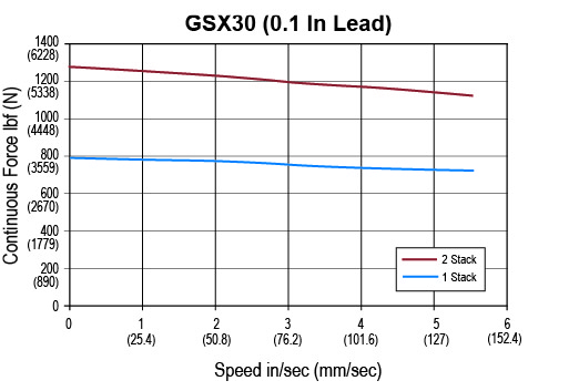
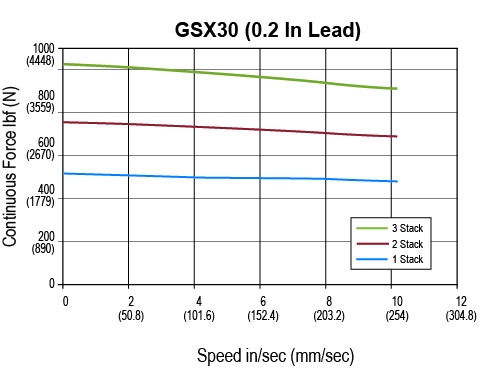
GSX30 Performance SpecificationsOpen arrow

GSX30 Performance Specifications

Motor Stacks   1 1 1 2 2 2 3 3
Screw Lead Designator   1 2 5 1 2 5 2 5
Screw Lead in 0.1 0.2 0.5 0.1 0.2 0.5 0.2 0.5
  mm 2.54 5.08 12.7 2.54 5.08 12.7 5.08 12.7
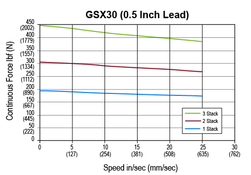
Continuous Force (Motor Limited) lbf 792 449 190 1277 724 306 1020 432
  N 3521 1995 845 5680 3219 1363 4537 1922
Max Velocity in/sec 5 10 25 5 10 25 10 25
  mm/sec 127 254 635 127 254 635 254 635
Friction Torque (standard screw) in-lbf 1.5 1.5 1.5 1.7 1.7 1.7 1.9 1.9
  N-m 0.17 0.17 0.17 0.19 0.19 0.19 0.21 0.21
Friction Torque (preloaded screw) in-lbf 3.3 3.3 3.3 3.5 3.5 3.5 3.7 3.7
  N-m 0.37 0.37 0.37 0.39 0.39 0.39 0.41 0.41
Min Stroke in 3 3 3 3 3 3 5.9 5.9
  mm 76 76 76 76 76 76 150 150
Max Stroke in 18 18 18 18 18 18 18 18
  mm 457 457 457 457 457 457 457 457
C_a (Dynamic Load Rating) lbf 5516 5800 4900 5516 5800 4900 5800 4900
  N 24536 25798 21795 24536 25798 21795 25798 21795
Inertia (zero stroke) lb-in-s^2 0.002655 0.002655 0.002655 0.002829 0.002829 0.002829 0.003003 0.003003
  Kg-m^2 0.0003 0.0003 0.0003 0.0003196 0.0003196 0.0003196 0.00033963 0.00033963
Inertia Adder (per inch of stroke) lb-in-s^2/in 0.0001424 0.0001424 0.0001424 0.0001424 0.0001424 0.0001424 0.0001424 0.0001424
  Kg-m^2/in 0.0000001609 0.0000001609 0.0000001609 0.0000001609 0.0000001609 0.0000001609 0.0000001609 0.0000001609
Weight (zero stroke) lb 6.5 6.5 6.5 7.65 7.65 7.65 8.8 8.8
  Kg 2.95 2.95 2.95 3.47 3.47 3.47 3.99 3.99
Weight Adder (per inch of stroke) lb 1.1 1.1 1.1 1.1 1.1 1.1 1.1 1.1
  Kg 0.5 0.5 0.5 0.5 0.5 0.5 0.5 0.5


GSX30 Electrical Speifications

Motor Stator   118 138 158 168 218 238 258 268 318 338 358 368
Bus Voltage Vrms 115 230 400 460 115 230 400 460 115 230 400 460
Speed @ Bus Voltage rpm 3000 3000 3000 3000 3000 3000 3000 3000 3000 3000 3000 3000
RMS Sinusoidal Commutation
Continuous Motor Torque lbf-in 16.9 16.8 16.3 16 26.9 27.1 26.7 27 38.7 38.2 36.2 36.3
  Nm 1.91 1.9 1.84 1.81 3.04 3.06 3.01 3.05 4.37 4.32 4.09 4.1
Torque Constant (Kt) (+/– 10% @ 25˚C) lbf-in/A 4.4 8.7 15.5 17.5 4.4 8.7 15.5 17.5 4.4 8.7 15.6 17.5
  Nm/A 0.49 0.99 1.75 1.97 0.49 0.99 1.75 1.97 0.5 0.98 1.77 1.98
Continuous Current Rating (Greased) A 4.3 2.2 1.2 1 6.9 3.5 1.9 1.7 9.7 4.9 2.6 2.3
  (Oil Cooled) A 8.6 4.3 2.4 2 13.8 6.9 3.8 3.4 19.5 9.9 5.2 4.6
Peak Current Rating A 8.6 4.3 2.4 2 13.8 6.9 3.8 3.4 19.5 9.9 5.2 4.6
O-Pk Sinusoidal Commutation
Continuous Motor Torque lbf-in 16.9 16.8 16.3 16 26.9 27.1 26.7 27 38.7 38.2 36.2 36.3
  Nm 1.91 1.9 1.84 1.81 3.04 3.06 3.01 3.05 4.37 4.32 4.09 4.1
Torque Constant (Kt) (+/– 10% @ 25˚C) lbf-in/A 3.1 6.2 11 12.4 3.1 6.2 11 12.4 3.1 6.1 11.1 12.4
  Nm/A 0.35 0.7 1.24 1.4 0.35 0.7 1.24 1.4 0.35 0.69 1.25 1.4
Continuous Current Rating: (Greased) A 6.1 3 1.7 1.4 9.7 4.9 2.7 2.4 13.8 7 3.7 3.3
  (Oil Cooled) A 12.2 6.1 3.3 2.9 19.5 9.8 5.4 4.9 27.6 13.9 7.3 6.5
Peak Current Rating A 12.2 6.1 3.3 2.9 19.5 9.8 5.4 4.9 27.6 13.9 7.3 6.5
Motor Stator Data
Voltage Constant (Ke) (+/– 10% @ 25˚C) Vrms/Krpm 29.8 59.7 105.8 119.3 29.8 59.7 105.8 119.3 30.3 59.2 106.8 119.8
  Vpk/Krpm 42.2 84.4 149.7 168.7 42.2 84.4 149.7 168.7 42.9 83.7 151 169.4
Pole Configuration   8 8 8 8 8 8 8 8 8 8 8 8
Resistance (L-L)(+/– 5% @ 25˚C) Ohms 2.7 10.8 36.3 47.9 1.1 4.4 14.1 17.6 0.65 2.6 9.3 11.6
Inductance (L-L)(+/– 15%) mH 7.7 30.7 96.8 123 3.7 14.7 46.2 58.7 2.5 9.5 30.9 38.8
Brake Inertia lbf-in-sec^2 0.00033 0.00033 0.00033 0.00033 0.00033 0.00033 0.00033 0.00033 0.00033 0.00033 0.00033 0.00033
  Kg-cm^2 0.38 0.38 0.38 0.38 0.38 0.38 0.38 0.38 0.38 0.38 0.38 0.38
Brake Current @ 24 VDC A 0.5 0.5 0.5 0.5 0.5 0.5 0.5 0.5 0.5 0.5 0.5 0.5
Brake Holding Torque (Min) lbf-in 40 40 40 40 40 40 40 40 40 40 40 40
  Nm 4.5 4.5 4.5 4.5 4.5 4.5 4.5 4.5 4.5 4.5 4.5 4.5
Brake Engage/Disengage Time ms 19/29 19/29 19/29 19/29 19/29 19/29 19/29 19/29 19/29 19/29 19/29 19/29
Mechanical Time Constant (tm), ms min 4.9 4.9 5.2 5.4 2 2 2 2 1.1 1.2 1.3 1.3
  max 9.4 9.5 10.1 10.5 3.9 3.8 3.9 3.8 2.2 2.3 2.5 2.5
Electrical Time Constant (te) ms 2.9 2.8 2.7 2.6 3.3 3.4 3.3 3.3 3.8 3.7 3.3 3.3
Insulation Class   180 (H) 180 (H) 180 (H) 180 (H) 180 (H) 180 (H) 180 (H) 180 (H) 180 (H) 180 (H) 180 (H) 180 (H)
For amplifiers using peak sinusoidal ratings, multiply RMS sinusoidal Kt by 0.707 and current by 1.414. Specifications subject to change without notice. Refer to performance specifications on page 9 for availability of 3 stack stator by stroke/lead combination. Test data derived using NEMA recommended aluminum heatsink 10" x 10" x 3/8" at 25°C ambient.
GSX40 Performance SpecificationsOpen arrow

GSX40 Performance Speficiations

Motor Stacks   1 1 1 1 2 2 2 2 3 3 3
Screw Lead Designator   1 2 5 8 1 2 5 8 2 5 8
Screw Lead in 0.1 0.2 0.5 0.75 0.1 0.2 0.5 0.75 0.2 0.5 0.75
  mm 2.54 5.08 12.7 19.05 2.54 5.08 12.7 19.05 5.08 12.7 19.05
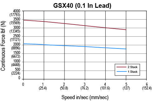
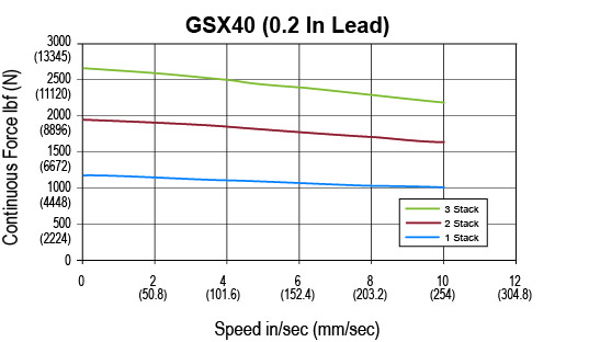
Continuous Force (Motor Limited) lbf 2089 1194 537 358 3457 1975 889 593 2687 1209 806
  N 9293 5310 2390 1593 15377 8787 3954 2636 11950 5378 3585
Max Velocity in/sec 5 10 25 37.5 5 10 25 37.5 10 25 37.5
  mm/sec 127 254 635 953 127 254 635 953 254 635 953
Friction Torque (standard screw) in-lbf 2.7 2.7 2.7 2.7 3 3 3 3 3.5 3.5 3.5
  N-m 0.31 0.31 0.31 0.31 0.34 0.34 0.34 0.34 0.4 0.4 0.4
Friction Torque (preloaded screw) in-lbf 7.2 7.2 7.2 7.2 7.5 7.5 7.5 7.5 8 8 8
  N-m 0.82 0.82 0.82 0.82 0.85 0.85 0.85 0.85 0.91 0.91 0.91
Min Stroke in 4 4 4 4 6 6 6 6 8 8 8
  mm 102 102 102 102 152 152 152 152 203 203 203
Max Stroke in 18 18 18 12 18 18 18 12 18 18 12
  mm 457 457 457 305 457 457 457 305 457 457 305
C_a (Dynamic Load Rating) lbf 7900 8300 7030 6335 7900 8300 7030 6335 8300 7030 6335
  N 35141 36920 31271 28179 35141 36920 31271 28179 36920 31271 28179
Inertia (zero stroke) lb-in-s^2 0.01132 0.01132 0.01132 0.01132 0.01232 0.01232 0.01232 0.01232 0.01332 0.01332 0.01332
  Kg-m^2 0.001279 0.001279 0.001279 0.001279 0.001392 0.001392 0.001392 0.001392 0.001505 0.001505 0.001505
Inertia Adder (per inch of stroke) lb-in-s^2/in 0.0005640 0.0005640 0.0005640 0.0005640 0.0005640 0.0005640 0.0005640 0.0005640 0.0005640 0.0005640 0.0005640
  Kg-m^2/in 0000006372
Weight (zero stroke) lb 8 8 8 8 11.3 11.3 11.3 11.3 14.6 14.6 14.6
  Kg 3.63 3.63 3.63 3.63 5.13 5.13 5.13 5.13 6.62 6.62 6.62
Weight Adder (per inch of stroke) lb 2 2 2 2 2 2 2 2 2 2 2
  Kg 0.91 0.91 0.91 0.91 0.91 0.91 0.91 0.91 0.91 0.91 0.91


GSX40 Electrical Specifications

Motor Stator   118 138 158 168 218 238 258 268 338* 358* 368*
Bus Voltage Vrms 115 230 400 460 115 230 400 460 230 400 460
Speed @ Bus Voltage rpm 3000 3000 3000 3000 3000 3000 3000 3000 3000 3000 3000
RMS Sinusoidal Commutation
Continuous Motor Torque lbf-in 47.5 47.5 45.9 45.4 75.1 78.6 78.7 79.5 106.9 105.3 106.9
  Nm 5.37 5.36 5.19 5.13 8.49 8.89 8.89 8.99 12.08 11.9 12.08
Torque Constant (Kt) (+/– 10% @ 25˚C) lbf-in/A 4.1 8.2 14.5 16.8 4.1 8.2 14.5 16.8 8.4 14.5 16.8
  Nm/A 0.46 0.93 1.64 1.9 0.46 0.93 1.64 1.9 0.95 1.64 1.9
Continuous Current Rating (Greased) A 12.9 6.5 3.5 3 20.5 10.7 6 5.3 14.2 8.1 7.1
  (Oil Cooled) A 25.9 12.9 7.1 6 40.9 21.4 12.1 10.6 28.5 16.2 14.2
Peak Current Rating A 25.9 12.9 7.1 6 40.9 21.4 12.1 10.6 28.5 16.2 14.2
O-Pk Sinusoidal Commutation
Continuous Motor Torque lbf-in 47.5 47.5 45.9 45.4 75.1 78.6 78.7 79.5 106.9 105.3 106.9
  Nm 5.37 5.36 5.19 5.13 8.49 8.89 8.89 8.99 12.08 11.9 12.08
Torque Constant (Kt) (+/– 10% @ 25˚C) lbf-in/A 2.9 5.8 10.3 11.9 2.9 5.8 10.3 11.9 5.9 10.3 11.9
  Nm/A 0.33 0.66 1.16 1.34 0.33 0.66 1.16 1.34 0.67 1.16 1.34
Continuous Current Rating (Greased) A 18.3 9.1 5 4.3 28.9 15.1 8.5 7.5 20.1 11.4 10.1
  (Oil Cooled) A 36.6 18.3 10 8.6 57.9 30.3 17.1 15 40.3 22.9 20.1
Peak Current Rating A 36.6 18.3 10 8.6 57.9 30.3 17.1 15 40.3 22.9 20.1
Motor Stator Data
Voltage Constant (Ke) (+/– 10% @ 25˚C) Vrms/Krpm 28 56 99.3 114.6 28 56 99.3 114.6 57.3 99.3 114.6
  Vpk/Krpm 39.6 79.2 140.5 162.1 39.6 79.2 140.5 162.1 81 140.5 162.1
Pole Configuration   8 8 8 8 8 8 8 8 8 8 8
Resistance (L-L)(+/– 5% @ 25˚C) Ohms 0.42 1.7 5.7 7.8 0.2 0.72 2.26 3 0.5 1.52 2
Inductance (L-L)(+/– 15%) mH 3 11.9 37.5 49.9 1.2 5.4 18.2 23.1 4 12 16
Brake Inertia lbf-in-sec^2 0.00096 0.00096 0.00096 0.00096 0.00096 0.00096 0.00096 0.00096 0.00096 0.00096 0.00096
  Kg-cm^2 1.08 1.08 1.08 1.08 1.08 1.08 1.08 1.08 1.08 1.08 1.08
Brake Current @ 24 VDC A 0.67 0.67 0.67 0.67 0.67 0.67 0.67 0.67 0.67 0.67 0.67
Brake Holding Torque (Min) lbf-in 97 97 97 97 97 97 97 97 97 97 97
  Nm 11 11 11 11 11 11 11 11 11 11 11
Brake Engage/Disengage Time ms 20/29 20/29 20/29 20/29 20/29 20/29 20/29 20/29 20/29 20/29 20/29
Mechanical Time Constant (tm), ms min 4.5 4.5 4.8 4.9 2.1 1.9 1.9 1.9 1.2 1.3 1.2
  max 6 6 6.4 6.6 2.8 2.6 2.6 2.5 1.7 1.7 1.7
Electrical Time Constant (te) ms 7 7 6.6 6.4 5.9 7.5 8 7.8 8.2 7.9 8.2
Insulation Class   180 (H) 180 (H) 180 (H) 180 (H) 180 (H) 180 (H) 180 (H) 180 (H) 180 (H) 180 (H) 180 (H)
Refer to performance specifications for availability of 3 stack stator by stroke/lead combination. Specifications subject to change without notice. Test data derived using NEMA recommended aluminum heatsink 12" x 12" x 1/2" at 25°C ambient.
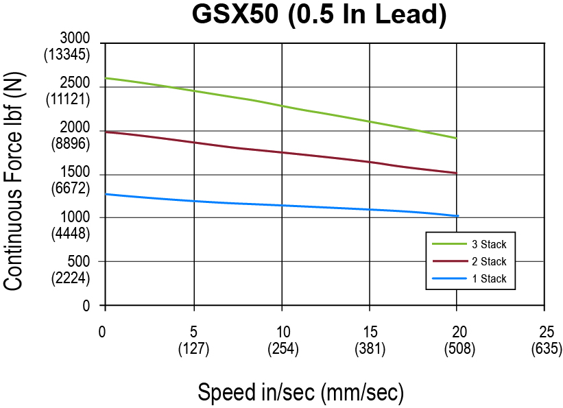
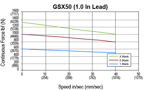
GSX50 Performance SpecificationsOpen arrow

GSX50 Performance Specifications

Motor Stacks   1 1 1 1 2 2 2 2 3 3 3
Screw Lead Designator   1 2 5 10 1 2 5 10 2 5 10
Screw Lead in 0.1 0.2 0.5 1 0.1 0.2 0.5 1 0.2 0.5 1
  mm 2.54 5.08 12.7 25.4 2.54 5.08 12.7 25.4 5.08 12.7 25.4
Continuous Force (Motor Limited) lbf 4399 2578 1237 619 7150 4189 2011 1005 5598 2687 1344
  N 19568 11466 5503 2752 31802 18634 8944 4472 24901 11953 5976
Max Velocity in/sec 4 8 20 40 4 8 20 40 8 20 40
  mm/sec 101.6 203 508 1016 101.6 203 508 1016 203 508 1016
Friction Torque (standard screw) in-lbf 4.1 4.1 4.1 4.1 4.6 4.6 4.6 4.6 5.3 5.3 5.3
  N-m 0.46 0.46 0.46 0.46 0.53 0.53 0.53 0.53 0.6 0.6 0.6
Friction Torque (preloaded screw) in-lbf 10.1 10.1 10.1 10.1 10.6 10.6 10.6 10.6 11.3 11.3 11.3
  N-m 1.14 1.14 1.14 1.14 1.21 1.21 1.21 1.21 1.36 1.36 1.36
Min Stroke in 6 6 6 6 6 6 6 6 10 10 10
  mm 152 152 152 152 152 152 152 152 254 254 254
Max Stroke in 10 14 14 10 10 14 14 10 14 14 10
  mm 254 356 356 254 254 356 356 254 356 356 254
C_a (Dynamic Load Rating) lbf 15693 13197 11656 6363 15693 13197 11656 6363 13197 11656 6363
  N 69806 58703 51848 28304 69806 58703 51848 28304 58703 51848 28304
Inertia (zero stroke) lb-in-s^2 0.02084 0.02084 0.02084 0.02084 0.023 0.023 0.023 0.023 0.02517 0.02517 0.02517
  Kg-m^2 0.002356 0.002356 0.002356 0.002356 0.002599 0.002599 0.002599 0.002599 0.002844 0.002844 0.002844
Inertia Adder (per inch of stroke) lb-in-s^2/in 0.001208
  Kg-m^2/in 0.0001365
Weight (zero stroke) lb 46 46 46 46 53 53 53 53 60 60 60
  Kg 20.87 20.87 20.87 20.87 24.04 24.04 24.04 24.04 27.2 27.2 27.2
Weight Adder (per inch of stroke) lb 3 3 3 3 3 3 3 3 3 3 3
  Kg 1.36 1.36 1.36 1.36 1.36 1.36 1.36 1.36 1.36 1.36 1.36


GSX50 Electrical Specifications

Motor Stator   138 158 168 238 258 268 338 358 368
Bus Voltage Vrms 230 400 460 230 400 460 230 400 460
Speed @ Bus Voltage rpm 2400 2400 2400 2400 2400 2400 2400 2400 2400
RMS Sinusoidal Commutation
Continuous Motor Torque lbf-in 107.2 104.8 109.4 179.9 178.8 177.8 233.3 237.2 238.3
  Nm 12.12 11.84 12.36 20.32 20.2 20.09 26.36 26.8 26.93
Torque Constant (Kt) (+/– 10% @ 25˚C) lbf-in/A 11.8 20.2 23.6 11.8 20.2 23.6 12 20.2 24
  Nm/A 1.33 2.28 2.67 1.33 2.28 2.67 1.36 2.28 2.71
Continuous Current Rating (Greased) A 10.2 5.8 5.2 17 9.9 8.4 21.7 13.1 11.1
  (Oil Cooled) A 20.3 11.6 10.4 34.1 19.8 16.8 43.4 26.2 22.2
Peak Current Rating A 20.3 11.6 10.4 34.1 19.8 16.8 43.4 26.2 22.2
O-Pk Sinusoidal Commutation
Continuous Motor Torque lbf-in 107.2 104.8 109.4 179.9 178.8 177.8 233.3 237.2 238.3
  Nm 12.12 11.84 12.36 20.32 20.2 20.09 26.36 26.8 26.93
Torque Constant (Kt) (+/– 10% @ 25˚C) lbf-in/A 8.3 14.3 16.7 8.3 14.3 16.7 8.5 14.3 17
  Nm/A 0.94 1.62 1.88 0.94 1.62 1.88 0.96 1.62 1.92
Continuous Current Rating (Greased) A 14.4 8.2 7.3 24.1 14 11.9 30.7 18.5 15.7
  (Oil Cooled) A 28.7 216.4 14.7 48.2 27.9 23.8 61.4 37.1 31.4
Peak Current Rating A 28.7 16.4 14.7 48.2 27.9 23.8 61.4 37.1 31.4
Motor Stator Data
Voltage Constant (Ke) (+/– 10% @ 25˚C) Vrms/Krpm 80.6 138.1 161.1 80.6 138.1 161.1 82 138.1 164
  Vpk/Krpm 113.9 195.3 227.9 113.9 195.3 227.9 116 195.3 232
Pole Configuration   8 8 8 8 8 8 8 8 8
Resistance (L-L)(+/– 5% @ 25˚C) Ohms 0.87 2.68 3.34 0.34 1.01 1.39 0.22 0.61 0.86
Inductance (L-L)(+/– 15%) mH 21.7 63.9 78.3 10.4 27.6 41.5 6.3 17.8 28.2
Brake Inertia lbf-in-sec^2 0.0084 0.0084 0.0084 0.0084 0.0084 0.0084 0.0084 0.0084 0.0084
  Kg-cm^2 9.5 9.5 9.5 9.5 9.5 9.5 9.5 9.5 9.5
Brake Current @ 24 VDC A 1 1 1 1 1 1 1 1 1
Brake Holding Torque (Min) lbf-in 354 354 354 354 354 354 354 354 354
  Nm 40 40 40 40 40 40 40 40 40
Brake Engage/Disengage Time ms 25/73 25/73 25/73 25/73 25/73 25/73 25/73 25/73 25/73
Mechanical Time Constant (tm), ms min 2.2 2.3 2.1 0.9 0.9 0.9 0.5 0.5 0.5
  max 2.8 3 2.7 1.1 1.1 1.1 0.7 0.7 0.7
Electrical Time Constant (te) ms 25 23.9 23.4 30.6 27.3 29.9 28 29 32.9
Insulation Class   180 (H) 180 (H) 180 (H) 180 (H) 180 (H) 180 (H) 180 (H) 180 (H) 180 (H)
Test data derived using NEMA recommended aluminum heatsink 12" x 12" x 1/2" at 25°C ambient Specifications subject to change without notice.
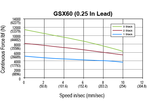
GSX60 Performance SpecificationsOpen arrow

GSX60 Performance Specifications

Motor Stacks   1 1 1 2 2 2 3 3 3
Screw Lead Designator   3 5 10 3 5 10 3 5 10
Screw Lead in 0.25 0.5 1 0.25 0.5 1 0.25 0.5 1
  mm 6.35 12.7 25.4 6.35 12.7 25.4 6.35 12.7 25.4
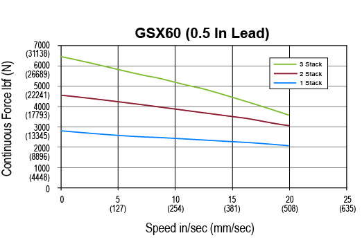
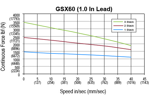
Continuous Force (Motor Limited) lbf 4937 2797 1481 8058 4566 2417 11528 6533 3459
  N 21958 12443 6588 35843 20311 10753 51278 29058 15383
Max Velocity in/sec 10 20 40 10 20 40 10 20 40
  mm/sec 254 508 1016 254 508 1016 254 508 1016
Friction Torque (standard screw) in-lbf 8.1 8.1 8.1 10.8 10.8 10.8 14.5 14.5 14.5
  N-m 0.91 0.91 0.91 1.22 1.22 1.22 1.64 1.64 1.64
Friction Torque (preloaded screw) in-lbf 14.1 14.1 14.1 16.8 16.8 16.8 20.5 20.5 20.5
  N-m 1.59 1.59 1.59 1.9 1.9 1.9 2.32 2.32 2.32
Min Stroke in 6 6 6 10 10 10 10 10 10
  mm 152 152 152 254 254 254 254 254 254
Max Stroke in 10 10 10 10 10 10 10 10 10
  mm 254 254 254 254 254 254 254 254 254
C_a (Dynamic Load Rating) lbf 25300 22800 21200 25300 22800 21200 25300 22800 21200
  N 112540 101420 94302 112540 101420 94302 112540 101420 94302
Inertia (zero stroke) lb-in-s^2 0.0804 0.0804 0.0804 0.1114 0.1114 0.1114 0.1424 0.1424 0.1424
  Kg-m^2 0.009087 0.009087 0.009087 0.01259 0.01259 0.01259 0.01609 0.01609 0.01609
Inertia Adder (per inch of stroke) lb-in-s^2/in 0.00519 0.00519 0.00519 0.00519 0.00519 0.00519 0.00519 0.00519 0.00519
  Kg-m^2/in 0.0005864 0.0005864 0.0005864 0.0005864 0.0005864 0.0005864 0.0005864 0.0005864 0.0005864
Weight (zero stroke) lb 48 48 48 62 62 62 76 76 76
  Kg 21.77 21.77 21.77 28.12 28.12 28.12 34.47 34.47 34.47
Weight Adder (per inch of stroke) lb 8 8 8 8 8 8 8 8 8
  Kg 3.63 3.63 3.63 3.63 3.63 3.63 3.63 3.63 3.63


GSX60 Electrical Specifications

Motor Stator   138 158 168 238 258 268 358 368
Bus Voltage Vrms 230 400 460 230 400 460 400 460
Speed @ Bus Voltage rpm 2400 2400 2400 2400 2400 2400 2400 2400
RMS Sinusoidal Commutation
Continuous Motor Torque lbf-in 254.2 249.9 261.9 424.8 423 427.5 595.6 615
  Nm 28.72 28.23 29.59 47.99 47.79 48.3 67.29 69.49
Torque Constant (Kt) (+/– 10% @ 25˚C) lbf-in/A 12.6 21.8 25.2 12.6 21.8 25.2 21.4 25.2
  Nm/A 1.42 2.46 2.84 1.42 2.46 2.84 2.42 2.84
Continuous Current Rating (Greased) A 22.6 12.8 11.6 37.7 21.7 19 31.1 27.3
  (Oil Cooled) A 45.2 25.6 23.3 75.5 43.4 38 62.2 54.6
Peak Current Rating A 45.2 25.6 23.3 75.5 43.4 38 62.2 54.6
O-Pk Sinusoidal Commutation
Continuous Motor Torque lbf-in 254.2 249.9 261.9 424.8 423 427.5 595.6 611.6
  (Nm) 28.72 28.23 29.59 47.99 47.79 48.3 67.29 69.1
Torque Constant (Kt) (+/– 10% @ 25˚C) lbf-in/A 8.9 15.4 17.8 8.9 15.4 17.8 15.1 17.8
  Nm/A 1.01 1.74 2.01 1.01 1.74 2.01 1.71 2.01
Continuous Current Rating (Greased) A 31.9 18.1 16.4 53.4 30.7 26.8 44 38.4
  (Oil Cooled) A 63.9 36.2 32.9 106.7 61.3 53.7 88 76.8
Peak Current Rating A 63.9 36.2 32.9 106.7 61.3 53.7 88 76.8
Motor Stator Data
Voltage Constant (Ke) (+/– 10% @ 25˚C) Vrms/Krpm 85.9 148.9 171.8 85.9 148.9 171.8 146.1 171.8
  Vpk/Krpm 121.5 210.6 243 121.5 210.6 243 206.6 243
Pole Configuration   8 8 8 8 8 8 8 8
Resistance (L-L)(+/– 5% @ 25˚C) Ohms 0.3 1 1.2 0.13 0.41 0.5 0.23 0.3
Inductance (L-L)(+/– 15%) mH 8.3 24.8 29.4 3.9 11.8 15.8 7.5 10.3
Brake Inertia lbf-in-sec^2 0.02815 0.02815 0.02815 0.02815 0.02815 0.02815 0.02815 0.02815
  Kg-cm^2 31.8 31.8 31.8 31.8 31.8 31.8 31.8 31.8
Brake Current @ 24 VDC A 1.45 1.45 1.45 1.45 1.45 1.45 1.45 1.45
Brake Holding Torque (Min) lbf-in 708 708 708 708 708 708 708 708
  Nm 80 80 80 80 80 80 80 80
Brake Engage/Disengage Time ms 53/97 53/97 53/97 53/97 53/97 53/97 53/97 53/97
Mechanical Time Constant (tm), ms min 3.9 4 3.6 1.6 1.6 1.6 1 0.9
  max 4.3 4.5 4.1 1.8 1.8 1.8 1.1 1
Electrical Time Constant (te) ms 25.4 24.6 24 29.4 29.1 29.8 32.1 33.8
Insulation Class   180 (H) 180 (H) 180 (H) 180 (H) 180 (H) 180 (H) 180 (H) 180 (H)
Test data derived using NEMA recommended aluminum heatsink 16" x 16" x 1" at 25°C ambient Specifications subject to change without notice. The GSX60-06 can only accommodate a single stack stator.

Product Literature

Catalogs, Brochures, and Success Stories

Industrial - Exlar, Brochures/Catalogs
Industrial - Exlar, Success Stories
No other electric actuator on the market could meet these high performance requirements.
Industrial - Exlar, Success Stories
Recognized leader in automated liquid dispensing systems replaces ball screw actuator with GSX series to improve the quality and life of their product, while reducing downtime and maintenance.
Industrial - Exlar, Case Studies
The GSX Series provides a wash-down compatible, sealed design in a compact package. Replacing the fluid power cylinders resulted in better performance, less maintenance, and longer life.
Show Resources

Actuator Technical Data

Manuals and Technical Tips

Industrial - Exlar, Software & Downloads
Industrial - Exlar, Actuator Technical Tips
Show Resources

Videos

Industrial - Exlar, Product Videos
Learn how we build our actuators
Industrial - Exlar, Product Videos
Exlar® actuators from Curtiss-Wright are an industry leader in electric actuation. Our research, pride, and creativity shine in this short video as we highlight our top product lines.
Industrial - Exlar, Product Videos
Ever wonder about the benefits of changing your system from hydraulic cylinders to electric actuation. We have the information you need.
Show Resources

Find more resources in our InfoCenter

How can we help?

Can you please provide a cost comparison between a ball screw and a roller screw actuator?Arrow
Cost comparison of a roller screw to a ball screw is really a difficult subject, mainly because we have to take into account the differences in the pieces that we are comparing. A roller screw is typically going to be competitive to a ball screw in regards to price because we can oftentimes use a roller screw that is smaller in size compared to its “equivalent” ball screw. This is because of the significant life advantage roller screws have. Therefore, if you are using a smaller frame size roller screw and comparing that to a larger size ball screw, with similar life expectancies, your pricing is going to be very similar. Now depending on what your needs are, if you are looking for something with much greater life, we’re not necessarily comparing an equal product. So you may have to buy two ball screws in comparison to one roller screw. If you look at that from a value standpoint, you may pay more for a similar frame size roller screw but you may have to buy two ball screws in the same period of time that you would have to buy that one roller screw.
How do you calculate the maximum duty cycle allowed vs the amount on current/force applied?Arrow

Below is the maximum-allowable duty cycle for your application given the percentage of input current over the continuous current rating:

For example: If your actuator has a continuous current rating of 10 A and a continuous force rating of 1000 lbf, this means it will take about 10 A to produce 1000 lbf of force, or 5 A to produce 500 lbf of force, and so on. What if you need to push more than 1000 lbf? In most cases, you would look at a stronger stator or a larger actuator. What if it’s only for a few seconds? Could you over-work the current actuator? Well the answer is yes, and calculating by how much isn’t too difficult.

Let’s say you need to push 1500 lbf. This would be equivalent to 1.5x the continuous current rating of 10 A. If you look below, the graph recommends no more than a 22% duty cycle in this case. This means you can run the actuator 22% of the time at 15 A without overheating. The other 78% of the time, it needs to be off/cooling.

How long can you run at peak current?

Not a simple question, nor a simple answer. In reality, so many things affect this (how the system is built and how well the actuator is able to dissipate heat, are there additional heat sinks, particles in the air, degree of vacuum, new starting temp each time? (i.e. doesn’t always start from cold, etc.). Therefore, accurate times and temperature are quite difficult to estimate.

For example: At peak current (2x Continuous), the allowable duty cycle is 4%. That doesn’t mean you can run for 4 hours straight as long as you have 96 hours of off time in between however. From experience, a good rule of thumb we’ve estimated is 30s to a minute of peak current run time. Try to keep it under that, and then of course allow it to cool for the other 96% of the time.

How does a roller screw compare to a hydraulic actuator of equal size and rate force?Arrow
That is going to depend on the application, but with equivalent specifications and characteristics, a roller screw actuator will typically be very similar in size to (sometimes slightly larger than) a comparable hydraulic cylinder. Hydraulics are always going to have their place in the market once you get beyond 100,000 lbs. of force, but anywhere an electromechanical roller screw actuator fits the bill, size will be very similar.
How long until my specific actuator/application needs to be serviced/re-greased?Arrow

We are asked about re-lubrication intervals a lot. The reality is that there is no generic interval to re-lube actuators. It depends on so many things and every application and situation is different, it is nearly impossible to accurately calculate a re-lube interval per application. So instead, we have a rough guideline table (shown below) to give users an idea on when to start checking for old contaminated grease that needs to be replaced. However, since ambient temperature, heat dissipation, speed variation, particles in the air, etc. can vary so much from application to application, this is only a guideline. The actuator should be checked more frequently around the period this table suggests and once it is noticed that the grease is ready to be replaced (Dirty, contaminated / very dark, filled with particles / debris) – a re-lube interval can be determined.

Remember, grease needs to be cleaned out and replaced – don’t just insert more. (Except for FTX’s, those can handle 5-6 greasings before they need to be cleaned out)

RMS ROTATIONAL SPEED (RPM) RECOMMENDED GREASE RENEWAL PERIOD (HOURS)
250 10,000
500 10,000
1000 8000
1500 7000
2000 5800
2500 5000
3000 4000
What are the primary benefits of using an electric actuator system over hydraulics?Arrow
Electric actuators offer high speed and force, are flexible and easily programmable for a variety of load conditions, have high accuracy and repeatability, are efficient, simple to install, require little maintenance, and are environmentally friendly.

By not using a hydraulic system, the user can eliminate oil leaks, reduce pollution, and improve worker safety. Electric actuators are also a non-toxic solution, especially in the food industry
What is the accuracy of the actuator?Arrow

A very common question for us. For the actuator itself, that is easy. There is a mechanical lead accuracy of the screw, which is usually 0.001 in/ft, a typical specification for precision positioning screws of any type. This means that at any point over the cumulative length of the screw, the lead will vary by a maximum of 0.001 inches per foot of screw length. This is not the same as mechanical repeatability. The mechanical repeatability is a tolerance on how close to the same linear position the screw will return, if approaching from the same direction, and driven exactly the same number of turns. This value is approximately 0.0004 inches.

The electronic positioning resolution is a function of the feedback device and the servo amplifier. Let’s assume that we have Exlar’s standard encoder on a GSX30 with 0.2 inches per revolution lead on the roller screw. Exlar’s standard encoder has 2048 lines and 8192 electronic pulses per revolution that it outputs to the servo drive. So in a perfect world, the positioning resolution would be (0.2 in/rev)/ (8192 pulses/rev) or 0.0000244 inches. Anyone who has used servo drives knows that you can’t position to one encoder pulse. Let’s use 10 encoder pulses as a reasonable best positioning capability. This gives us a positioning resolution of 0.000244 inches.

More things to consider: When addressing repeatability and accuracy, several things must also be taken into account. One of these is the stiffness of the system. Stiffness is how much the system will stretch or compress under compressive or tensile forces. If the combination of the stiffness of the actuator and the stiffness of the mechanical system, including all couplings, mounting surface, etc. allows for more compression or stretch than the required positioning resolution of the system, obtaining acceptable positioning results will be nearly impossible. Another consideration is thermal expansion and contraction. Consider a GS actuator attached to a tool that is doing a precision grinding process. Assuming that the tool is steel and 12 inches long, a 5 degree rise in temperature will cause the tool to expand by 0.0006 inches. If the system is programmed to make 0.0002 inch moves, this expansion could cause serious positioning problems. The same applies to the components of the actuator itself. The actuator rod can change in temperature from a cold start up to running temperature. This change may need to be accounted for in very precise positioning applications.

What is the maintenance schedule life for a typical roller screw?Arrow
The maintenance schedule for any geared mechanical device, whether ball screw, roller screw, or gearhead, is going to be based on the amount of heat that is generated in the application, the amount of degradation of the grease, the type of grease being used, and the duty cycle. We provide some guidelines for our customers as starting points, but we recommend that for all new installations the lubrication be periodically inspected for presence and degradation as the best method for determining the right maintenance schedule for a given application. Having said that, we’ve seen repairs of units that have been in use for 15 years and when we’ve asked about grease renewal, they didn’t even realize that the unit could be serviced in the field. So we’ve had situations like that where they’ve gone for long periods of time with effectively no maintenance or no grease renewal. There are other applications that require grease renewal in very short intervals just due to the nature of the application.
What keeps the output shaft from rotating?Arrow
On a conventional roller screw design package, there typically is an anti-rotation groove designed into the housing, and a tab designed into the nut that rides in the housing groove as the actuator extends and retracts. In regards to the inverted roller screw design, part of the installation or the application requirement is going to be having that shaft solidly mounted a machine coupling or tooling on the machine otherwise providing some sort of external anti-rotation device on that output shaft. There are other ways of using splines and different types of non-circular output shafts that can allow for different types of spline nuts that will provide anti-rotation, but typically you’re going to see that mounted on the machine.
How do I estimate life of the actuator?Arrow
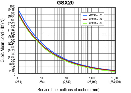
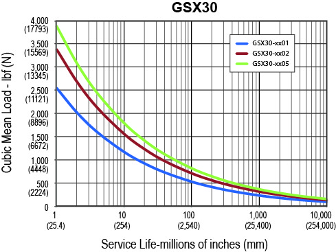
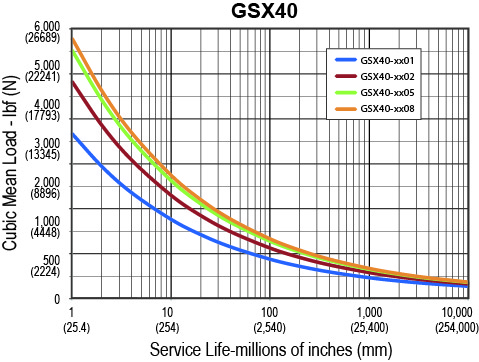
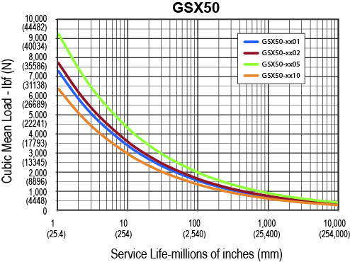
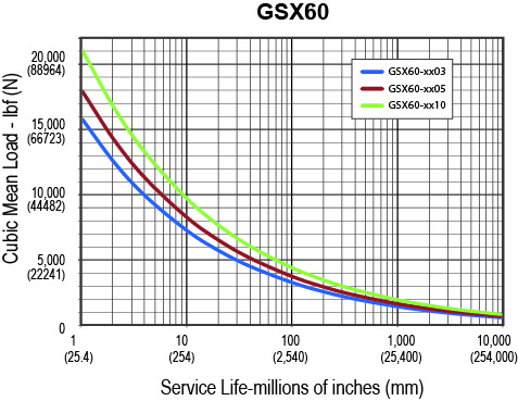
The L10 expected life of a roller screw linear actuator is expressed as the linear travel distance that 90% of properly maintained roller screws manufactured are expected to meet or exceed. This calculation should be used for estimation purposes only.

The underlying formula that defines this value is: Travel life in millions of inches, where:
Ca= Dynamic load rating (lbf)
Fcml= Cubic mean applied load (lbf)
ℓ = Roller screw lead (inches)

For additional details on calculating estimated service life, please refer www.cw-actuation.com.

L10=(Ca)3 x ℓ Fcm

This site uses cookies to improve our service, you can find out more here - for the best web experience please accept cookies

x