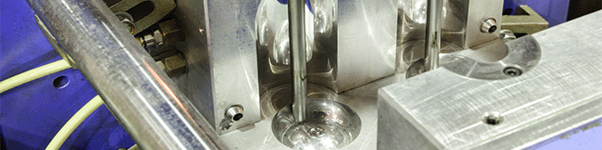
液压缸提供长寿命和高力小的封装尺寸。该系列FTX力高电动执行器是专门设计,让从传统的液压驱动电动迁移。基于行星滚柱丝杠技术,提供FTX生活和力密度与基于更常见的滚珠丝杠电动执行机构无法达到。凭借高达15倍的寿命和2X力密度,基于FTX滚柱丝杠是液压迁移到电力驱动时的正确选择
| 型 | 框架尺寸(毫米) | 行程 毫米(英寸) | 最大連續力 kN (磅力) | 最大速度毫米/秒(英寸/秒) |
| FTX095 | 95 (3.7) | 150 (6), 300 (12), 600 (24), 900 (36), 1200 (48) | 22 (5,000) | 1,500 (59.3) |
| FTX125 | 125 (5.0) | 150 (6), 300 (12), 600 (24), 900 (36), 1200 (48) | 44 (10,000) | 583 (23.0) |
| FTX160 | 160 (6.3) | 150 (6), 300 (12), 600 (24), 900 (36), 1200 (48) | 89 (20,000) | 1,000 (39.0) |
| FTX215 | 215 (8.5) | 150 (6), 300 (12), 600 (24), 900 (36), 1200 (48) | 178 (40,000) | 875 (34.0) |
液压缸通常安装在恶劣的工业设置。因此,所有FTX系列型号环境密封等级为IP65。另外,它的行星辊式丝杠机构承受显著更高冲击载荷弱于滚珠丝杠的替代品。迁移到电有信心知道FTX系列是每一位坚固,可靠,因为它们是设计来取代液压。
越来越多的机器制造商正在寻找消除液压油泄漏有关的混乱和停机时间。电力驱动,不仅消除了液体泄漏相关的问题,它提供了显著更高水平的性能和灵活性,可能比甚至与伺服液压解决方案。FTX系列滚柱丝杠驱动器让机器制造商满足其客户不断增长的性能需求,同时最大限度地减少或消除与传统的液压解决方案相关的维护问题。
| 楷模: | FTX095, FTX125, FTX160, FTX215 |
| 外形尺寸: | 95 mm (3.74 in), 125 mm (5 in), 160 mm (6.3 in) 215 mm (8.5 in) |
| 螺丝信息: | 5, 6, 10, 12, 20, 30 毫米 (.20, .25, .39, .50, .79, 1.18 英寸) |
| 行程长度: | 150, 300, 600, 900, 1200 毫米 (6, 12, 24, 36, 48 英寸 ) |
| 线速度: | 高达 1500 毫米/秒 (59 英寸/秒) |
| 最大力量: | 高达 178 千牛 (40,000 磅力) |
| 标准/评分: | IP65S |
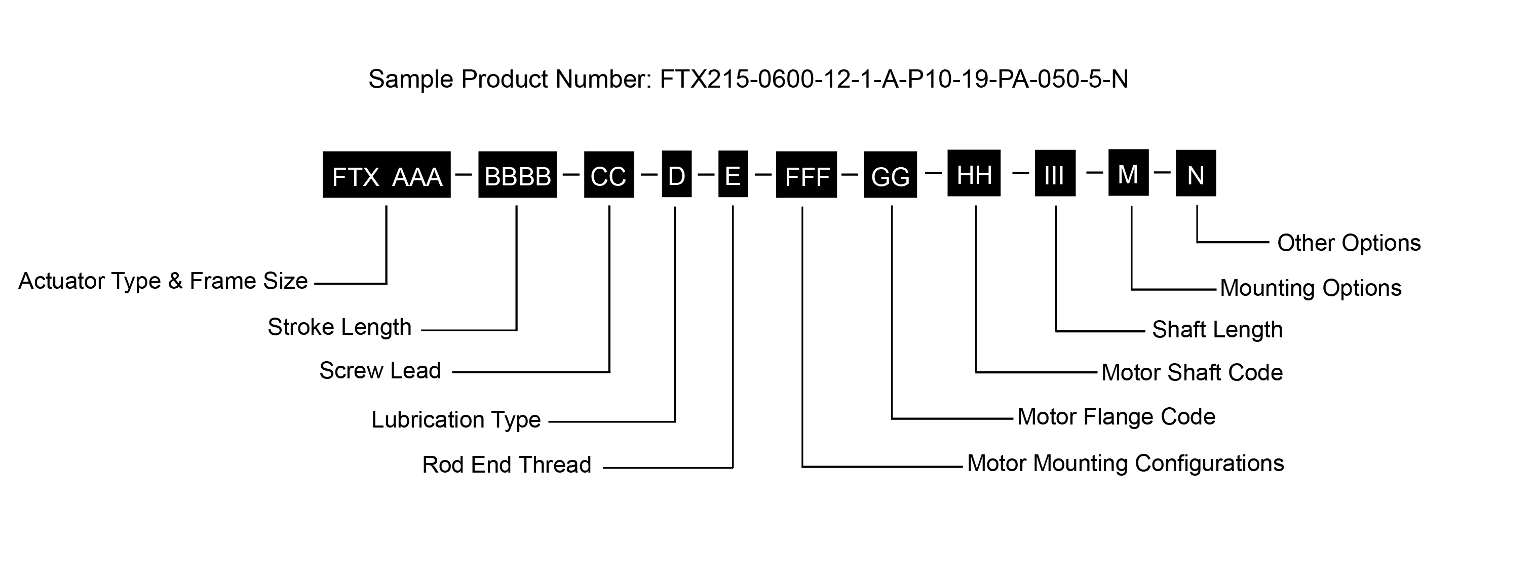 | |
AAA = Frame Size | FFF = Motor Mounting Configurations1 |
笔记 :
1. 始终与您当地的销售代表讨论您的电机选择。
2. 不提供直列式或 NMT 电机安装座,请联系您当地的销售代表。
3. 可用选项。 可增加交货时间
* 某些选项并非在每个配置中都可用。 对于上面未列出的选项或特价,请联系您当地的 Exlar 代表.
可调外部行程开关
外部行程开关指示到控制器的行程,并可针对原点或终端位置进行调节。
前安装法兰
前安装法兰,包括用于端面安装的通孔
后夹板,公制
后夹板安装座,允许执行器在运动时旋转
后眼安装
后眼安装座,允许执行器在运动时旋转
后耳轴安装座
A 后耳轴是一个圆柱形突起,用作安装或枢轴点。
润滑脂
FTX 系列执行器出厂时,使用高温润滑脂进行完全润滑。 Exlar 使用美孚力富 SHC 220,这是一种高性能的极压润滑脂。
低温润滑脂
对于低温应用,FTX 系列使用美孚润滑脂 28。 该润滑脂适用于环境温度范围内 -40°C 至 85°C 的执行器应用。
机油
FTX 系列使用美孚 SHC 626 进行机油加注。 执行器是空的,仅从工厂收到用于初始测试的轻质油涂层。
| 5 | 10 | 20 | ||
|---|---|---|---|---|
| Screw Lead | mm | 5 | 10 | 20 |
| in | 0.197 | 0.394 | 0.787 | |
| Maximum Force* | kN | 22.2 | 22.2 | 22.2 |
| lbf | 5,000 | 5,000 | 5,000 | |
| Life at Maximum Force | km | 392 | 626 | 1440 |
| in x 10^6 | 15.4 | 24.6 | 56.7 | |
| C_a (Dynamic Load Rating) | kN | 95.2 | 88.3 | 92.5 |
| lbf | 21,400 | 19,850 | 20,800 | |
| Maximum Input Torque | Nm | 22.1 | 44.3 | 88.5 |
| lbf-in | 196 | 392 | 783 | |
| Max Rated RPM @ Input Shaft | RPM | 4,500 | 4,500 | 4,500 |
| Maximum Linear Speed @ Maximum Rated RPM | mm/sec | 373 | 750 | 1,500 |
| in/sec | 14.7 | 29.5 | 59.3 | |
| Friction Torque | Nm | 1.12 | 1.12 | 1.12 |
| lbf-in | 10 | 10 | 10 |
| kg | lb | |
|---|---|---|
| Base Actuator Weight (Zero Stroke) | 10 | 21 |
| Actuator Weight Adder (Per 25 mm of stroke) | 0.39 | 0.87 |
| Adder for Inline (excluding motor) | 2.9 | 6.5 |
| Adder for Parallel Drive (excluding motor) | 13.1 | 28.9 |
| Adder for Front Flange | 1.9 | 4.2 |
| Adder for Rear Clevis | 5.3 | 11.7 |
| Adder for Rear Eye | 5.1 | 11.3 |
| Adder for Rear Trunnion | 1.9 | 4.3 |
| Base Unit Inertia | Zero Stroke [kg-m^2 (lbf-in-sec^2)] | Add per 25 mm [kg-m^2 (lbf-in-sec^2)] | |
|---|---|---|---|
| —5 mm Lead | 8.27 x 10^-4 (7.32 x 10^-3) | 2.19 x 10^-6 (1.94 x 10^-5) | |
| —10 mm Lead | 8.33 x 10^-4 (7.37 x 10^-3) | 2.42 x 10^-6 (2.14 x 10^-5) | |
| —20 mm Lead | 8.57 x 10^-4 (7.58 x 10^-3) | 3.31 x 10^-6 (2.93 x 10^-5) | |
| Inline Drive Inertia | Inline Unit - w/Motor Coupling | Inline Unit - w/Motor Coupling For Gearbox Mount | Add per 25 mm |
| —5 mm Lead | 9.27 x 10^-4 (8.20 x 10^-3) | 1.09 x 10^-3 (9.62 x 10^-3) | 2.19 x 10^-6 (1.94 x 10^-5) |
| —10 mm Lead | 9.33 x 10^-4 (8.26 X 10^-3) | 1.09 x 10^-3 (9.67 x 10^-3) | 2.42 x 10^-6 (2.14 x 10^-5) |
| —20 mm Lead | 9.57 x 10^-4 (8.47 x 10^-3) | 1.12 x 10^-3 (9.89 x 10^-3) | 3.31 x 10^-6 (2.93 x 10^-5) |
| Parallel Drive Inertia | 1:1 Reduction | 2:1 Reduction | |
| —5 mm Lead (zero stroke) | 4.90 x 10^-3 (4.34 x 10^-2) | 2.22 x 10^-3 (1.97 x 10^-2) | |
| ——Add per 25 mm stroke | 2.19 x 10^-6 (1.94 x 10^-5) | 5.48 x 10^-7 (4.85 x 10^-6) | |
| —10 mm Lead (zero stroke) | 4.91 x 10^-3 (4.34 x 10^-2) | 2.23 x 10^-3 (1.97 x 10^-2) | |
| ——Add per 25 mm stroke | 2.42 x 10^-6 (2.14 x 10^-5) | 6.04 x 10^-7 (5.34 x 10^-6) | |
| —20 mm Lead (zero stroke) | 4.93 x 10^-3 (4.37 x 10^-2) | 2.23 x 10^-3 (1.98 x 10^-2) | |
| ——Add per 25 mm stroke | 3.31 x 10^-6 (2.93 x 10^-5) | 8.28 x 10^-7 (7.33 x 10^-6) |
| 5 | 10 | ||
|---|---|---|---|
| Screw Lead | mm | 5 | 10 |
| in | 0.197 | 0.394 | |
| Maximum Force* | kN | 44.5 | 44.5 |
| lbf | 10,000 | 10,000 | |
| Life at Maximum Force | km | 249.2 | 486.3 |
| in x 10^6 | 9.81 | 19.14 | |
| C_a (Dynamic Load Rating)* | kN | 163.7 | 162.4 |
| lbf | 36,800 | 36,500 | |
| Maximum Input Torque | Nm | 46.5 | 82.3 |
| lbf-in | 412 | 728 | |
| Max Rated RPM @ Input Shaft |
RPM | 3,500 | 3,500 |
| Maximum Linear Speed @ Maximum Rated RPM | mm/sec | 292 | 583 |
| in/sec | 11.5 | 23 | |
| Friction Torque | Nm | 2.23 | 2.23 |
| lbf-in | 20 | 20 |
| C_a Derating | |||
|---|---|---|---|
| FTX125 | 05 | 10 | |
| *C_a (Dynamic Load Rating) Greater than 900mm Stroke | kN | 143.4 |
162.4 |
| lbf | 32,240 | 36,500 | |
| kg | lb | |
|---|---|---|
| Base Actuator Weight (Zero Stroke) | 21 | 47 |
| Actuator Weight Adder (Per 25 mm of stroke) | 0.84 | 1.85 |
| Adder for Inline (excluding motor) | 6.8 | 15 |
| Adder for Parallel Drive (excluding motor) | 25.6 | 56.5 |
| Adder for Front Flange | 3.6 | 7.9 |
| Adder for Rear Clevis | 6.5 | 14.3 |
| Adder for Rear Eye | 6.3 | 13.8 |
| Adder for Rear Trunnion | 3.1 | 6.8 |
| Base Unit Inertia | Zero Stroke [kg-m^2 (lb-in-s^2)] | Add per 25 mm [kg-m^2 (lb-in-s^2)] | |
|---|---|---|---|
| —5 mm Lead | 2.55 x 10^-3 (2.26 x 10^-2) | 4.62 x 10^-5 (4.09 x 10^-4) | |
| —10 mm Lead | 2.56 x 1^0-3 (2.27 x 10^-2) | 4.65 x 10^-5 (4.12 x 10^-4) | |
| Inline Drive Inertia | <32 mm Motor Shaft Diameter | >32 mm Motor Shaft Diameter | Add per 25 mm |
| —5 mm Lead | 2.81 x 10^-3 (2.49 x 10^-2) | 3.35 x 10^-3 (2.97 x 10^-2) | 4.62 x 10^-5 (4.09 x 10^-4) |
| —10 mm Lead | 2.82 x 10^-3 (2.50 x 10^-2) | 3.36 x 10^-3 (2.98 x 10^-2) | 4.65 x 10^-5 (4.12 x 10^-4) |
| Parallel Drive Inertia | 1:1 Reduction | 2:1 Reduction | |
| —5 mm Lead (zero stroke) | 9.43 x 10^-3 (8.34 x 10^-2) | 4.66 x 10⁻³ (4.12 x 10⁻²) | |
| ——Add per 25 mm stroke | 4.62 x 10^-5 (4.09 x 10^-4) | 1.15 x 10^-5 (1.02 x 10^-4) | |
| —10 mm Lead (zero stroke) | 9.44 x 10^-3 (8.35 x 10^-2) | 4.66 x 10^-3 (4.13 x 10^-2) | |
| ——Add per 25 mm stroke | 4.65 x 10^-5 (4.12 x 10^-4) | 1.16 x 10^-5 (1.03 x 10^-4) |
| 6 | 12 | 30 | ||
|---|---|---|---|---|
| Screw Lead | mm | 6 | 12 | 30 |
| in | 0.236 | 0.472 | 1.181 | |
| Maximum Force* | kN | 89 | 89 | 89 |
| lbf | 20,000 | 20,000 | 20,000 | |
| Life at Maximum Force | km | 154.9 | 416.6 | 358.9 |
| in x 10^6 | 6.1 | 16.4 | 21.2 | |
| C_a (Dynamic Load Rating)* | kN | 263.7 | 290.0 | 233.0 |
| lbf | 59,275 | 65,200 | 52,400 | |
| Maximum Input Torque | Nm | 106 | 212 | 531 |
| lbf-in | 940 | 1,880 | 4,699 | |
| Max Rated RPM @ Input Shaft |
RPM | 2,000 | 2,000 | 2,000 |
| Maximum Linear Speed @ Maximum Rated RPM | mm/sec | 201 | 401 | 1,000 |
| in/sec | 7.9 | 15.8 | 39.0 | |
| Friction Torque | Nm | 4.54 | 4.54 | 4.54 |
| lbf-in | 40 | 40 | 40 |
| C_a Derating | ||||
|---|---|---|---|---|
| FTX160 | 06 | 12 | 30 | |
| *C_a (Dynamic Load Rating) Greater than 900mm Stroke | kN | 223.6 | 261.2 | 233 |
| lbf | 50,270 | 58,720 | 52,400 | |
| kg | LB | |
|---|---|---|
| Base Actuator Weight (Zero Stroke) | 49 | 108 |
| Actuator Weight Adder (Per 25 mm of stroke) | 1.62 | 3.6 |
| Adder for Inline (excluding motor) | 14.2 | 31.5 |
| Adder for Parallel Drive (excluding motor) | 53.1 | 117.8 |
| Adder for Front Flange | 7.4 | 16.4 |
| Adder for Rear Clevis | 21.2 | 48.8 |
| Adder for Rear Eye | 22.4 | 49.7 |
| Adder for Rear Trunnion | 10.9 | 24.2 |
| Base Unit Inertia | Zero Stroke [kg-m^2 (lbf-in-sec^2)] | Add per 25 mm [kg-m^2 (lbf-in-sec^2)] | |
|---|---|---|---|
| 6 mm Lead | 1.35 x 10^-2 (1.19 x 10^-1) | 2.57 x 10^-4 (2.27 x 10^-3) | |
| 12 mm Lead | 1.35 x 10^-2 (1.20 x 10^-1) | 2.58 x 10^-4 (2.28 x 10^-3) | |
| 30 mm Lead | 1.38 x 10^-2 (1.22 x 10^-1) | 2.66 x 10^-4 (2.36 x 10^-3) | |
| Inline Drive Inertia | <32 mm Motor Shaft Diameter | >32 mm Motor Shaft Diameter | Add per 25 mm |
| 6 mm Lead | 1.47 x 10^-2 (1.30 x 10^-1) | 1.67 x 10^-2 (1.48 x 10^-1) | 2.57x 10^-4 (2.27 x 10^-3) |
| 12 mm Lead | 1.47 x 10^-2 (1.30 x 10^-1) | 1.68 x 10^-2 (1.49 x 10^-1) | 2.58 x 10^-4 (2.28 x 10^-3) |
| 30 mm Lead | 1.50 x 10^-2 (1.33 x 10^-1) | 1.71 x 10^-2 (1.51 x 10^-1) | 2.66 x 10^-4 (2.36 x 10^-3) |
| Parallel Drive Inertia | 1:1 Reduction | 2:1 Reduction | |
| —6 mm Lead (zero stroke) | 5.27 x 10^-2 (4.67 x 10^-1) | 2.30 x 10^-2 (2.04 x 10^-1) | |
| ——Add per 25 mm stroke | 2.57 x 10^-4 (2.27 x 10^-3) | 6.42 x 10^-5 (5.68 x 10^-4) | |
| —12 mm Lead (zero stroke) | 5.28 x 10^-2 (4.67 x 10^-1) | 2.30 x 10^-2 (2.04 x 10^-1) | |
| ——Add per 25 mm stroke | 2.58 x 10^-4 (2.28 x 10^-3) | 6.45 x 10^-5 (5.71 x 10^-4) | |
| —30 mm Lead (zero stroke) | 5.30 x 10^-2 (4.69 x 10^-1) | 2.31 x 10^-2 (2.05 x 10^-1) | |
| ——Add per 25 mm stroke | 2.66 x 10^-4 (2.36 x 10^-3) | 6.66 x 10^-5 (5.89 x 10^-4) |
| 6 | 12 | 30 | ||
|---|---|---|---|---|
| Screw Lead | mm | 6 | 12 | 30 |
| in | 0.236 | 0.472 | 1.181 | |
| Maximum Force* | kN | 177.9 | 177.9 | 177.9 |
| lbf | 40,000 | 40,000 | 40,000 | |
| Life at Maximum Force | km | 78.7 | 161.8 | 414.3 |
| in x 10^6 | 3.1 | 6.4 | 16.3 | |
| C_a (Dynamic Load Rating)* | kN | 398 | 423 | 376 |
| lbf | 89,500 | 95,200 | 84,700 | |
| Maximum Input Torque | Nm | 243 | 425 | 976 |
| lbf-in | 2,148 | 3,760 | 8,642 | |
| Max Rated RPM @ Input Shaft |
RPM | 1,750 | 1,750 | 1,750 |
| Maximum Linear Speed @ Maximum Rated RPM | mm/sec | 175 | 351 | 875 |
| in/sec | 6.9 | 13.8 | 34.4 | |
| Friction Torque | Nm | 5.65 | 5.65 | 5.65 |
| lbf-in | 50 | 50 | 50 |
| C_a Derating | ||||
|---|---|---|---|---|
| FTX215 | 06 | 12 | 30 | |
| *C_a (Dynamic Load Rating) Greater than 900mm Stroke | kN | 359.8 | 346.7 | 376 |
| lbf | 80,900 | 77,950 | 84,700 | |
| kg | lb | |
|---|---|---|
| Base Actuator Weight (Zero Stroke) | 103 | 227 |
| Actuator Weight Adder (Per 25 mm of stroke) | 2.70 | 5.96 |
| Adder for Inline (excluding motor) | 38.6 | 85.1 |
| Adder for Parallel Drive (excluding motor) | 62.3 | 137.3 |
| Adder for Front Flange | 26.7 | 58.8 |
| Adder for Rear Clevis | 32.5 | 71.6 |
| Adder for Rear Eye | 32.5 | 71.6 |
| Adder for Rear Trunnion | 9.6 | 212 |
| Base Unit Inertia | Zero Stroke [kg-m^2 (lbf-in-sec^2)] | Add per 25 mm [kg-m^2 (lbf-in-sec^2)] |
|---|---|---|
| 6 mm Lead | Add per 25 mm, 6 mm Lead | |
| Base Unit - Input Drive Shaft Only | 4.25 x 10^2 (3.76 x 10^1) | 8.00 x 10^4 (7.08 x 10^3) |
| 12 mm Lead | Add per 25 mm, 12 mm Lead | |
| Base Unit - Input Drive Shaft Only | 4.26 x 10^2 (3.77 x 10^1) | 8.02 x 10^4 (7.10 x 10^3) |
| 30 mm Lead | Add per 25 mm, 30 mm Lead | |
| Base Unit - Input Drive Shaft Only | 4.31 x 10^2 (3.82 x 10^1) | 8.15 x 10^4 (7.21 x 10^3) |
| Inline Drive Inertia | 6 mm Lead | Add per 25 mm, 6 mm Lead |
| Inline Unit - w/Motor Coupling | 4.43 x 10^2 (3.92 x 10^1) | 8.00 x 10^4 (7.08 x 10^3) |
| Inline Unit - w/Motor Coupling >55mm Shaft Diameter | 6.15 x 10^2 (5.44 x 10^1) | 8.00 x 10^4 (7.08 x 10^3) |
| 12 mm Lead | Add per 25 mm, 12 mm Lead | |
| Inline Unit - w/Motor Coupling | 4.44 x 10^2 (3.93 x 10^1) | 8.02 x 10^4 (7.10 x 10^3) |
| Inline Unit - w/Motor Coupling >55mm Shaft Diameter | 6.16 x 10^2 (5.45 x 10^1) | 8.02 x 10^4 (7.10 x 10^3) |
| 30 mm Lead | Add per 25 mm, 30 mm Lead | |
| Inline Unit - w/Motor Coupling | 4.49 x 10^2 (3.98 x 10^1) | 8.15 x 10^4 (7.21 x 10^3) |
| Inline Unit - w/Motor Coupling >55mm Shaft Diameter | 6.21 x 10^2 (5.50 x 10^1) | 8.15 x 10^4 (7.21 x 10^3) |
| Parallel Drive Inertia | 6 mm Lead | Add per 25 mm, 6 mm Lead |
| 1:1 Reduction Parallel Belt Drive | 8.73 x 10^2 (7.72 x 10^1) | 8.00 x 10^4 (7.08 x 10^3) |
| 2:1 Reduction Parallel Belt Drive | 3.14 x 10^2 (2.78 x 10^1) | 2.00 x 10^4 (1.77 x 10^3) |
| 12 mm Lead | Add per 25 mm, 12 mm Lead | |
| 1:1 Reduction Parallel Belt Drive | 8.74 x 10^2 (7.73 x 10^1) | 8.02 x 10^4 (7.10 x 10^3) |
| 2:1 Reduction Parallel Belt Drive | 3.14 x 10^2 (2.78 x 10^1) | 2.01 x 10^4 (1.78 x 10^3) |
| 30 mm Lead | Add per 25 mm, 30 mm Lead | |
| 1:1 Reduction Parallel Belt Drive | 8.79 x 10^2 (7.78 x 10^1) | 8.15 x 10^4 (7.21 x 10^3) |

以下是给定输入电流占比连续额定电流百分比时,您的应用的最大允许占空比:
例如: 如果您的执行器的连续额定电流为 10 A,连续额定力为 1000 lbf,则意味着产生 1000 lbf 的力需要大约 10 A,产生 500 lbf 的力需要 5 A,依此类推。 如果您需要推动超过1000磅的重量怎么办? 在大多数情况下,您会考虑更强的定子或更大的致动器。 如果只有几秒钟呢? 您是否会过度使用当前的执行器? 答案是肯定的,计算多少并不难。
假设您需要推动1500 lbf。 这相当于10 A连续额定电流的1.5倍。 如果您看下面,图表建议在这种情况下占空比不超过22%。 这意味着您可以在15 A电流下运行执行器22%的时间而不会过热。 另外78%的时间,它需要关闭/冷却。

在峰值电流下可以运行多长时间?
不是一个简单的问题,也不是一个简单的答案。 实际上,影响这一点的因素有很多(系统是如何构建的,执行器散热的能力如何,是否有额外的散热器,空气中的颗粒,真空度,每次新的启动温度? (即并不总是从冷开始等)。 因此,精确的时间和温度很难估计。
例如: 在峰值电流(2x连续)时,允许的占空比为4%。 这并不意味着只要您有96个小时的休息时间,您就可以连续跑步4小时。 根据经验,我们估计的一个很好的经验法则是峰值电流运行时间为30秒到一分钟。 试着把它放在下面,然后当然让它冷却96%的时间。
我们经常被问及再润滑间隔。 现实情况是,没有通用的间隔来重新润滑执行器。 它取决于很多事情,每个应用和情况都不同,几乎不可能准确计算每个应用的再润滑间隔。 因此,我们有一个粗略的指南表(如下所示),让用户了解何时开始检查需要更换的旧污染润滑脂。 但是,由于环境温度,散热,速度变化,空气中的颗粒等可能因应用而异,因此这只是一个指南。 在此表建议的时间段内,应更频繁地检查致动器,一旦注意到润滑脂已准备好更换(脏污,污染/非常暗,充满颗粒/碎屑), 就可以确定重新润滑间隔。
请记住,润滑脂需要清理和更换 - 不要只是插入更多。 (除了FTX,在需要清理之前,它们可以处理5-6个润滑)
| 均方根转速 (转速) | 建议的润滑脂更新期(小时) |
|---|---|
| 250 | 10,000 |
| 500 | 10,000 |
| 1000 | 8000 |
| 1500 | 7000 |
| 2000 | 5800 |
| 2500 | 5000 |
| 3000 | 4000 |
对我们来说,这是一个非常普遍的问题。 对于执行器本身来说,这很容易。 螺钉的机械导程精度通常为0.001 in/ft,这是任何类型的精密定位螺钉的典型规格。 这意味着在螺钉累积长度的任意点上,每英尺螺钉长度的最大变化为 0.001 英寸。 这与机械可重复性不同。 机械可重复性是螺钉从同一方向接近并驱动完全相同的匝数时,螺钉返回的相同线性位置的公差。 此值约为 0.0004 英寸。
电子定位分辨率是反馈装置和伺服放大器的功能。 假设我们在GSX30上有Exlar的标准编码器,滚柱丝杠上每转引线为0.2英寸。 Exlar 的标准编码器每转有 2048 条线路和 8192 个电子脉冲,可输出到伺服驱动器。 因此,在理想情况下,定位分辨率将为(0.2英寸/转)/(8192脉冲/转)或0.0000244英寸。 任何使用过伺服驱动器的人都知道,您不能定位到一个编码器脉冲。 让我们使用10个编码器脉冲作为合理的最佳定位能力。 这为我们提供了0.000244英寸的定位分辨率。
需要考虑的更多事项: 在考虑可重复性和准确性时,还必须考虑几个因素。 其中之一是系统的刚度。 刚度是系统在压缩力或拉伸力下拉伸或压缩的程度。 如果执行器的刚度和机械系统的刚度(包括所有联轴器、安装面等)的组合允许比系统所需的定位分辨率更多的压缩或拉伸,那么获得可接受的定位结果几乎是不可能的。 另一个考虑因素是热膨胀和收缩。 考虑一个GS执行器连接到正在执行精密磨削过程的刀具上。 假设工具是钢的,长12英寸,温度升高5度将导致工具膨胀0.0006英寸。 如果系统被编程为进行0.0002英寸的移动,则这种扩展可能会导致严重的定位问题。 这同样适用于执行器本身的组件。 执行器杆的温度可以从冷启动到运行温度变化。 在非常精确的定位应用中,可能需要考虑这种变化。
Please log in or register to use our quote request tool, with this you can view and download 3D and 2D models and drawings, as well as build and submit a quote request.
If you do not have a login, please proceed to the registration page
RegisterIf you currently have an Exlar website account and would like to delete it, please contact


.jpg "FTX095-Estimated-Service-Life-(1).jpg")


.jpg "FTX125-Estimated-Service-Life-(1).jpg")


.jpg "FTX160-Estimated-Service-Life-(1).jpg")


.jpg "FTX215-Estimated-Service-Life-(1).jpg")