Industrial - Exlar
好处:型 | 框架尺寸(毫米) | 行程毫米(英寸) | 最大連續力 kN (磅力) | 最大速度毫米/秒(英寸/秒) |
| KX60 | 60 (2.36) | 150 (6), 300 (12), 600 (24), 900 (36) | 6 (1,350) | 833 (32.8 ) |
| KX75 | 75 (2.95) | 150 (6), 300 (12), 600 (24), 900 (36) | 11.1 (2,500) | 666 (26.2) |
| KX90 | 90 (3.54) | 150 (6), 300 (12), 600 (24), 900 (36) | 15.6 (3,500) | 500 (19.7) |
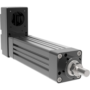
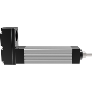
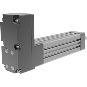
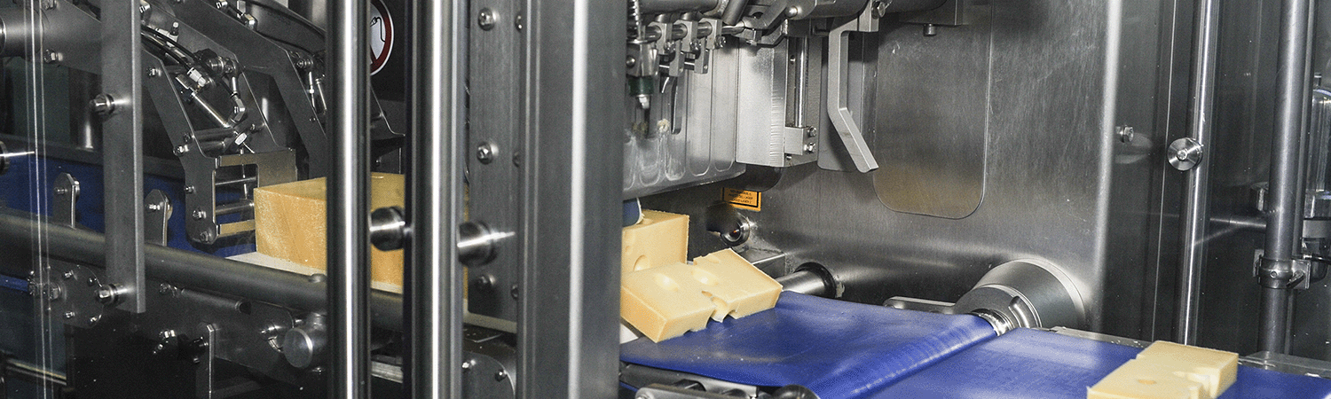
滾柱絲杠執行器具有幾個優點,適用於許多應用,特別是那些涉及重負載和快速迴圈的應用。 其他優點包括系統佔地面積小、功能壽命長和維護要求低。 由於滾柱絲杠系統不需要高壓流體,因此它們可以降低噪音水平,並且不會受到潛在危險流體洩漏的影響。
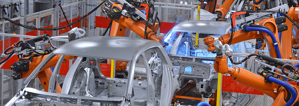
這些堅固的電動執行器是氣動缸的理想替代品,並具有具有相似外形尺寸的可比尺寸。 更好的性能、更大的靈活性和更長的使用壽命最終使 K 系列成為許多應用的明智選擇。 KX級高性能行星滾柱絲杠的性能遠遠優於競爭對手的執行器技術。 這些執行器是 Exlar 自動化、行動裝置、程式控制和許多其他要求苛刻的應用的理想選擇。
其他優勢
而構建應用
KX級高性能行星滾柱絲杠的性能遠遠優於競爭對手的執行器技術。 因此,這些執行器是一系列要求苛刻的應用的理想選擇,包括:
| 型号: | KX60, KX75, KX90(高容量滚柱丝杠执行器) KM60, KM75, KM90(标准容量滚柱丝杠执行器)- 传统产品 |
| 框架尺寸: | 2.3, 2.9, 3.5英寸(60, 75, 90毫米) |
| 行程长度: | 150, 300, 600, 900 毫米 (6, 12, 24, 36 英寸 ) |
| 线性速度: | 高达32.8英寸/秒(833毫米/秒) |
| 最大力: | 高达3,500磅力(15千牛) |
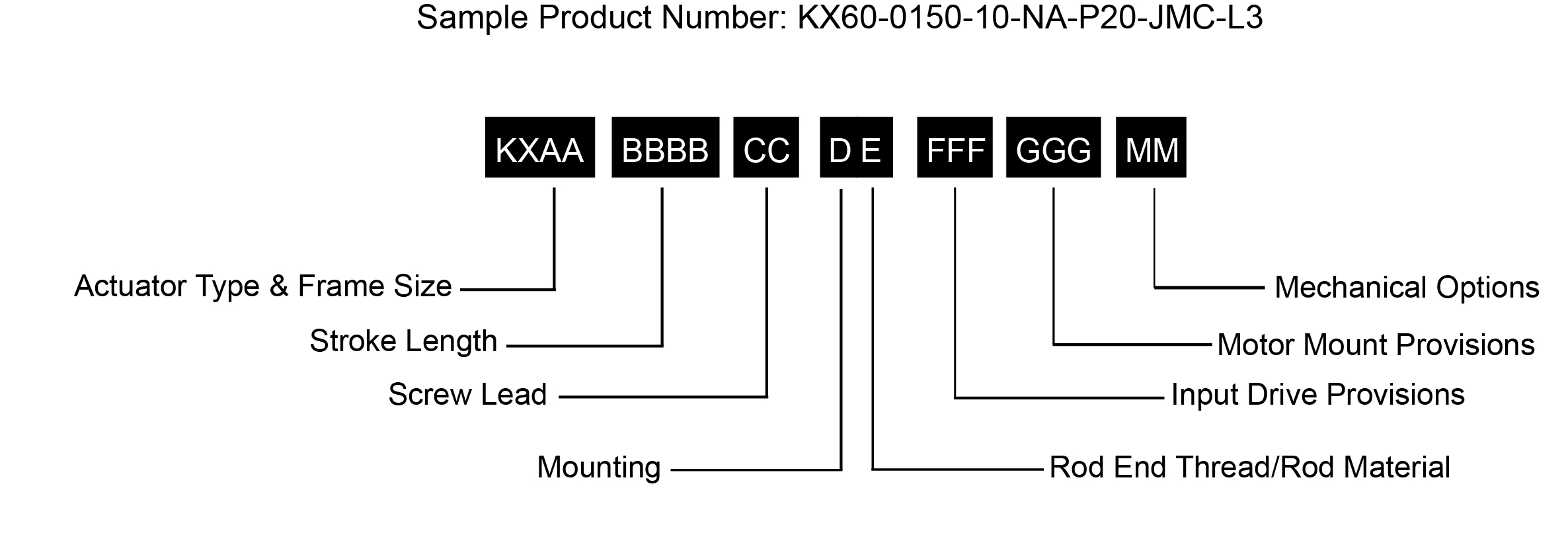 | |
AA = Actuator Frame Size | FFF = Input Drive Provisions |
笔记 :
1. 对于超大尺寸电机,请联系您当地的销售代表。
2. 有关扩展温度操作,请咨询工厂以获取型号。
* 某些选项并非在每个配置中都可用。 对于上面未列出的选项或特价,请联系您当地的 Exlar 代表.
L1、L2、L3 = 可调外部行程开关
外部行程开关指示到控制器的行程,并可针对原点或终端位置进行调节。
| Models | KX | KM - Legacy Product | |||
|---|---|---|---|---|---|
| Screw Lead | in | 0.1969 | 0.3937 | 0.1969 | 0.3937 |
| mm | 5 | 10 | 5 | 10 | |
| Maximum Force^2 | lbf | 1350 | 675 | 1350 | 675 |
| kN | 6 | 3 | 6 | 3 | |
| Life at Maximum Force | in x 10^6 | 1.6 | 18.2 | 0.4 | 4.5 |
| km | 41.7 | 461.4 | 10.4 | 115.3 | |
| C_a (Dynamic Load Rating) | lbf | 2738 | 2421 | 1725 | 1525 |
| kN | 12.2 | 10.8 | 7.7 | 6.8 | |
| Maximum Input Torque^1 | lbf-in | 53 | 53 | 53 | 53 |
| Nm | 6 | 6 | 6 | 6 | |
| Max Rated RPM @ Input Shaft | RPM | 5000 | 5000 | 5000 | 5000 |
| Maximum Linear Speed @ Maximum Rated RPM | in/sec | 16.4 | 32.8 | 16.4 | 32.8 |
| mm/sec | 417 | 833 | 417 | 833 | |
| kg-m^-2 (lbf-in-sec^-2) | kg-m^-2 (lbf-in-sec^-2) | |
|---|---|---|
| 5 mm Lead | Add per 25 mm, 5 mm Lead | |
| Base Unit - Input Drive Shaft Only | 1.480 x 10^-5 (1.31 x 10^-4) | 1.022 x 10^-6 (9.045 x 10^-6) |
| Inline Unit - w/Motor Coupling | 2.702 x 10^-5 (2.39 x 10^-4) | 1.022 x 10^-6 (9.045 x 10^-6) |
| 10 mm Lead | Add per 25 mm, 10 mm Lead | |
| Base Unit - Input Drive Shaft Only | 1.616 x 10^-5 (1.43 x 10^-4) | 1.173 x 10^-6 (1.038 x 10^-5) |
| Inline Unit - w/Motor Coupling | 2.837 x 10^-5 (2.51 x 10^-4) | 1.173 x 10^-6 (1.038 x 10^-5) |
| Parallel Drive Inertias (P10 Option) | ||
| 5 mm Lead | Add per 25 mm, 5 mm Lead | |
| 1:1 Reduction Parallel Belt Drive (66 mm) | 4.339 x 10^-5 (3.84 x 10^-4) | 1.022 x 10^-6 (9.045 x 10^-6) |
| 1:1 Reduction Parallel Belt Drive (86 mm) | 7.378 x 10^-5 (6.53 x 10^-4) | 1.022 x 10^-6 (9.045 x 10^-6) |
| 1:1 Reduction Parallel Belt Drive (96 mm) | 8.564 x 10^-5 (7.58 x 10^-4) | 1.022 x 10^-6 (9.045 x 10^-6) |
| 2:1 Reduction Parallel Belt Drive (96 mm) | 7.095 x 10^-5 (6.28 x 10^-4) | 2.555 x 10^-7 (2.261 x 1^-6) |
| 10 mm Lead | Add per 25 mm, 10 mm Lead | |
| 1:1 Reduction Parallel Belt Drive (66 mm) | 4.474 x 10^-5 (3.96 x 10^-4) | 1.173 x 10^-6 (1.038 x 10^-5) |
| 1:1 Reduction Parallel Belt Drive (86 mm) | 7.514 x 10^-5 (6.65 x 10^-4) | 1.173 x 10^-6 (1.038 x 10^-5) |
| 1:1 Reduction Parallel Belt Drive (96 mm) | 8.704 x 10^-5 (7.70 x 10^-4) | 1.173 x 10^-6 (1.038 x 10^-5) |
| 2:1 Reduction Parallel Belt Drive (96 mm) | 1.966 x 10^-5 (1.74 x 10^-4) | 2.931 x 10^-7 (2.595 x 10^-6) |
| Parallel Drive Inertias (Smooth Motor Shaft Option) | ||
| 5 mm Lead | Add per 25 mm, 5 mm Lead | |
| 1:1 Reduction Parallel Belt Drive (66 mm) | 6.015 x 10^-5 (5.32 x 10^-4) | 1.022 x 10^-6 (9.045 x 10^-6) |
| 1:1 Reduction Parallel Belt Drive (86 mm) | 1.103 x 10^-4 (9.76 x 10^-4) | 1.022 x 10^-6 (9.045 x 10^-6) |
| 1:1 Reduction Parallel Belt Drive (96 mm) | 2.176 x 10^-4 (1.93 x 10^-3) | 1.022 x 10^-6 (9.045 x 10^-6) |
| 2:1 Reduction Parallel Belt Drive (96 mm) | 8.768 x 10^-5 (7.76 x 10^-4) | 2.555 x 10^-7 (2.261 x 10^-6) |
| 10 mm Lead | Add per 25 mm, 10 mm Lead | |
| 1:1 Reduction Parallel Belt Drive (66 mm) | 6.150 x 10^-5 (5.44 x 10^-4) | 1.173 x 10^-6 (1.038 x 10^-6) |
| 1:1 Reduction Parallel Belt Drive (86 mm) | 1.117 x 10^-4 (9.88 x 10^-4) | 1.173 x 10^-6 (1.038 x 10^-6) |
| 1:1 Reduction Parallel Belt Drive (96 mm) | 2.190 x 10^-4 (1.94 x 10^-3) | 1.173 x 10^-6 (1.038 x 10^-6) |
| 2:1 Reduction Parallel Belt Drive (96 mm) | 8.802 x 10^-5 (7.79 x 10^-4) | 2.931 x 10^-7 (2.595 x 10^-6) |
| lb | kg | |
|---|---|---|
| Base Actuator Weight (Zero Stroke) | 3.7 | 1.7 |
| Actuator Weight Adder (Per mm of Stroke) | 0.017 | 0.008 |
| Adder for Inline (excluding motor) | 0.93 | 0.42 |
| Adder for Parallel Drive (excluding motor) | 1.6 | 0.73 |
| Adder for Front Flange | 0.93 | 0.42 |
| Adder for Rear Clevis | 0.98 | 0.44 |
| Adder for Two Trunnions | 0.72 | 0.33 |
.jpg "K60-Critical-Speed-(1).jpg")
.jpg "K60-Maximum-Radial-(1).jpg")
.jpg "K60-Rated-Force-(1).jpg")
| Models | KX | KM - Legacy Product | |||
|---|---|---|---|---|---|
| Screw Lead | in | 0.1969 | 0.3937 | 0.1969 | 0.3937 |
| mm | 5 | 10 | 5 | 10 | |
| Maximum Force^2 | lbf | 2500 | 1250 | 2500 | 1250 |
| kN | 11.1 | 5.6 | 11.1 | 5.6 | |
| Life at Maximum Force | in x 10^6 | 2.4 | 22.6 | 0.6 | 5.6 |
| km | 60.7 | 573.3 | 15.2 | 143.5 | |
| C_a (Dynamic Load Rating) | lbf | 5746 | 4820 | 3620 | 3036 |
| kN | 25.6 | 21.4 | 16.1 | 13.5 | |
| Maximum Input Torque^1 | lbf-in | 98 | 98 | 98 | 98 |
| Nm | 11 | 11 | 11 | 11 | |
| Max Rated RPM @ Input Shaft | RPM | 4000 | 4000 | 4000 | 4000 |
| Maximum Linear Speed @ Maximum Rated RPM | in/sec | 13.1 | 26.2 | 13.1 | 26.2 |
| mm/sec | 333 | 666 | 333 | 666 | |
| kg-m^-2 (lbf-in-sec^-2) | kg-m^-2 (lbf-in-sec^-2) | |
|---|---|---|
| 5 mm Lead | Add per 25 mm, 5 mm Lead | |
| Base Unit - Input Drive Shaft Only | 9.26 x 10^-5 (8.20 x 10^-4) | 3.13 x 10^-6 (2.77 x 10^-5) |
| Inline Unit - w/Motor Coupling | 1.25 x 10^-4 (1.11 x 10^-3) | 3.13 x 10^-6 (2.77 x 10^-5) |
| 10 mm Lead | Add per 25 mm, 10 mm Lead | |
| Base Unit - Input Drive Shaft Only | 9.48 x 10^-5 (8.39 x 10^-4) | 3.32 x 10^-6 (2.94 x 10^-5) |
| Inline Unit - w/Motor Coupling | 1.44 x 10^-4 (1.28 x 10^-3) | 3.32 x 10^-6 (2.94 x 10^-5) |
| Parallel Drive Inertias (P10 Option) | ||
| 5 mm Lead | Add per 25 mm, 5 mm Lead | |
| 1:1 Reduction Parallel Belt Drive (86 mm) | 2.29 x 10^-4 (2.03 x 10^-3) | 3.13 x 10^-6 (2.77 x 10^-5) |
| 1:1 Reduction Parallel Belt Drive (96 mm) | 3.19 x 10^-4 (2.82 x 10^-3) | 3.13 x 10^-6 (2.77 x 10^-5) |
| 1:1 Reduction Parallel Belt Drive (130 mm) | 5.96 x 10^-4 (5.28 x 10^-3) | 3.13 x 10^-6 (2.77 x 10^-5) |
| 2:1 Reduction Parallel Belt Drive (130 mm) | 2.82 x 10^-4 (2.50 x 10^-3) | 7.83 x 10^-7 (6.93 x 10^-6) |
| 10 mm Lead | Add per 25 mm, 10 mm Lead | |
| 1:1 Reduction Parallel Belt Drive (86 mm) | 2.31 x 10^-4 (2.05 x 10^-3) | 3.32 x 10^-6 (2.94 x 10^-5) |
| 1:1 Reduction Parallel Belt Drive (96 mm) | 3.21 x 10^-4 (2.84 x 10^-3) | 3.32 x 10^-6 (2.94 x 10^-5) |
| 1:1 Reduction Parallel Belt Drive (130 mm) | 5.98 x 10^-4 (5.30 x 10^-3) | 3.32 x 10^-6 (2.94 x 10^-5) |
| 2:1 Reduction Parallel Belt Drive (130 mm) | 2.83 x 10^-4 (2.51 x 10^-3) | 8.30 x 10^-7 (7.36 x 10^-6) |
| Parallel Drive Inertias (Smooth Motor Shaft Option) | ||
| 5 mm Lead | Add per 25 mm, 5 mm Lead | |
| 1:1 Reduction Parallel Belt Drive (86 mm) | 2.84 x 10^-4 (2.51 x 10^-3) | 3.13 x 10^-6 (2.77 x 10^-5) |
| 1:1 Reduction Parallel Belt Drive (96 mm) | 4.25 x 10^-4 (3.76 x 10^-3) | 3.13 x 10^-6 (2.77 x 10^-5) |
| 1:1 Reduction Parallel Belt Drive (130 mm) | 7.33 x 10^-4 (6.48 x 10^-3) | 3.13 x 10^-6 (2.77 x 10^-5) |
| 2:1 Reduction Parallel Belt Drive (130 mm) | 3.32 x 10^-4 (2.94 x 10^-3) | 7.83 x 10^-7 (6.93 x 10^-6) |
| 10 mm Lead | Add per 25 mm, 10 mm Lead | |
| 1:1 Reduction Parallel Belt Drive (86 mm) | 2.86 x 10^-4 (2.53 x 10^-3) | 3.32 x 10^-6 (2.94 x 10^-5) |
| 1:1 Reduction Parallel Belt Drive (96 mm) | 4.27 x 10^-4 (3.78 x 10^-3) | 3.32 x 10^-6 (2.94 x 10^-5) |
| 1:1 Reduction Parallel Belt Drive (130 mm) | 7.35 x 10^-4 (6.50 x 10^-3) | 3.32 x 10^-6 (2.94 x 10^-5) |
| 2:1 Reduction Parallel Belt Drive (130 mm) | 3.33 x 10^-4 (2.94 x 10^-3) | 8.30 x 10^-7 (7.35 x 10^-6) |
| lb | kg | |
|---|---|---|
| Base Actuator Weight (Zero Stroke) | 6.75 | 3.06 |
| Actuator Weight Adder (Per mm of Stroke) | 0.0235 | 0.0107 |
| Adder for Inline (excluding motor) | 2.46 | 1.12 |
| Adder for Parallel Drive (excluding motor) | 4.06 | 1.84 |
| Adder for Front Flange | 1.91 | 0.87 |
| Adder for Rear Clevis | 1.85 | 0.84 |
| Adder for Two Trunnions | 1.56 | 0.71 |
.jpg "K75-Critical-Speed-(1).jpg")
.jpg "K75-Maximum-Radial-(1).jpg")
.jpg "K75-Rated-Force-(1).jpg")
| Models | KX | KM - Legacy Product | |||
|---|---|---|---|---|---|
| Screw Lead | in | 0.1969 | 0.3937 | 0.1969 | 0.3937 |
| mm | 5 | 10 | 5 | 10 | |
| Maximum Force^2 | lbf | 3500 | 1750 | 3500 | 1750 |
| kN | 15.6 | 7.8 | 15.6 | 7.8 | |
| Life at Maximum Force | in x 10^6 | 7.1 | 90.4 | 1.8 | 22.6 |
| km | 179.6 | 2295 | 44.9 | 573.8 | |
| C_a (Dynamic Load Rating) | lbf | 11548 | 10715 | 7275 | 6750 |
| kN | 51.4 | 47.7 | 32.4 | 30 | |
| Maximum Input Torque^1 | lbf-in | 137 | 137 | 137 | 137 |
| Nm | 16 | 16 | 16 | 16 | |
| Max Rated RPM @ Input Shaft | RPM | 3000 | 3000 | 3000 | 3000 |
| Maximum Linear Speed @ Maximum Rated RPM | in/sec | 9.8 | 19.7 | 9.8 | 19.7 |
| mm/sec | 250 | 500 | 250 | 500 | |
| kg-m^-2 (lbf-in-sec^-2) | kg-m^-2 (lbf-in-sec^-2) | |
|---|---|---|
| 5 mm Lead | Add per 25 mm, 5 mm Lead | |
| Base Unit - Input Drive Shaft Only | 2.97 x 10^-4 (2.63 x 10^-3) | 1.11 x 10^-5 (9.80 x 10^-5) |
| Inline Unit - w/Motor Coupling | 3.84 x 10^-4 (3.40 x 10^-3) | 1.11 x 10^-5 (9.80 x 10^-5) |
| 10 mm Lead | Add per 25 mm, 10 mm Lead | |
| Base Unit - Input Drive Shaft Only | 3.00 x 10^-4 (2.66 x 10^-3) | 1.13 x 10^-5 (1.00 x 10^-4) |
| Inline Unit - w/Motor Coupling | 3.87 x 10^-4 (3.43 x 10^-3) | 1.13 x 10^-5 (1.00 x 10^-4) |
| Parallel Drive Inertias (P10 Option) | ||
| 5 mm Lead | Add per 25 mm, 5 mm Lead | |
| 1:1 Reduction Parallel Belt Drive (96 mm) | 5.12 x 10^-4 (4.53 x 10^-3) | 1.11 x 10^-5 (9.80 x 10^-5) |
| 1:1 Reduction Parallel Belt Drive (130 mm) | 7.98 x 10^-4 (7.07 x 10^-3) | 1.11 x 10^-5 (9.80 x 10^-5) |
| 2:1 Reduction Parallel Belt Drive (130 mm) | 3.41 x 10^-4 (3.02 x 10^-3) | 2.77 x 10^-6 (2.45 x 10^-5) |
| 10 mm Lead | Add per 25 mm, 10 mm Lead | |
| 1:1 Reduction Parallel Belt Drive (96 mm) | 5.15 x 10^-4 (4.56 x 10^-3) | 1.13 x 10^-5 (1.00 x 10^-4) |
| 1:1 Reduction Parallel Belt Drive (130 mm) | 8.02 x 10^-4 (7.10 x 10^-3) | 1.13 x 10^-5 (1.00 x 10^-4) |
| 2:1 Reduction Parallel Belt Drive (130 mm) | 3.42 x 10^-4 (3.03 x 10^-3) | 2.82 x 10^-6 (2.50 x 10^-5) |
| Parallel Drive Inertias (Smooth Motor Shaft Option) | ||
| 5 mm Lead | Add per 25 mm, 5 mm Lead | |
| 1:1 Reduction Parallel Belt Drive (96 mm) | 6.18 x 10^-4 (5.47 x 10^-3) | 1.11 x 10^-5 (9.80 x 10^-5) |
| 1:1 Reduction Parallel Belt Drive (130 mm) | 9.35 x 10^-4 (8.27 x 10^-3) | 1.11 x 10^-5 (9.80 x 10^-5) |
| 2:1 Reduction Parallel Belt Drive (130 mm) | 3.91 x 10^-4 (3.46 x 10^-3) | 2.77 x 10^-6 (2.45 x 10^-5) |
| 10 mm Lead | Add per 25 mm, 10 mm Lead | |
| 1:1 Reduction Parallel Belt Drive (96 mm) | 6.21 x 10^-4 (5.50 x 10^-3) | 1.13 x 10^-5 (1.00 x 10^-4) |
| 1:1 Reduction Parallel Belt Drive (130 mm) | 9.38 x 10^-4 (8.30 x 10^-3) | 1.13 x 10^-5 (1.00 x 10^-4) |
| 2:1 Reduction Parallel Belt Drive (130 mm) | 3.92 x 10^-4 (3.47 x 10^-3) | 2.82 x 10^-6 (2.50 x 10^-5) |
| lb | kg | |
|---|---|---|
| Base Actuator Weight (Zero Stroke) | 11.96 | 5.42 |
| Actuator Weight Adder (Per mm of Stroke) | 0.0366 | 0.016 |
| Adder for Inline (excluding motor) | 3.35 | 1.51 |
| Adder for Parallel Drive (excluding motor) | 5.8 | 2.62 |
| Adder for Front Flange | 3.4 | 1.54 |
| Adder for Rear Clevis | 3.21 | 1.45 |
| Adder for Two Trunnions | 1.768 | 0.8 |
.jpg "K90-Critical-Speed-(1).jpg")
.jpg "K90-Maxium-Radial-(1).jpg")
.jpg "K90-Rated-Force-(1).jpg")

以下是给定输入电流占比连续额定电流百分比时,您的应用的最大允许占空比:
例如: 如果您的执行器的连续额定电流为 10 A,连续额定力为 1000 lbf,则意味着产生 1000 lbf 的力需要大约 10 A,产生 500 lbf 的力需要 5 A,依此类推。 如果您需要推动超过1000磅的重量怎么办? 在大多数情况下,您会考虑更强的定子或更大的致动器。 如果只有几秒钟呢? 您是否会过度使用当前的执行器? 答案是肯定的,计算多少并不难。
假设您需要推动1500 lbf。 这相当于10 A连续额定电流的1.5倍。 如果您看下面,图表建议在这种情况下占空比不超过22%。 这意味着您可以在15 A电流下运行执行器22%的时间而不会过热。 另外78%的时间,它需要关闭/冷却。

在峰值电流下可以运行多长时间?
不是一个简单的问题,也不是一个简单的答案。 实际上,影响这一点的因素有很多(系统是如何构建的,执行器散热的能力如何,是否有额外的散热器,空气中的颗粒,真空度,每次新的启动温度? (即并不总是从冷开始等)。 因此,精确的时间和温度很难估计。
例如: 在峰值电流(2x连续)时,允许的占空比为4%。 这并不意味着只要您有96个小时的休息时间,您就可以连续跑步4小时。 根据经验,我们估计的一个很好的经验法则是峰值电流运行时间为30秒到一分钟。 试着把它放在下面,然后当然让它冷却96%的时间。
我们经常被问及再润滑间隔。 现实情况是,没有通用的间隔来重新润滑执行器。 它取决于很多事情,每个应用和情况都不同,几乎不可能准确计算每个应用的再润滑间隔。 因此,我们有一个粗略的指南表(如下所示),让用户了解何时开始检查需要更换的旧污染润滑脂。 但是,由于环境温度,散热,速度变化,空气中的颗粒等可能因应用而异,因此这只是一个指南。 在此表建议的时间段内,应更频繁地检查致动器,一旦注意到润滑脂已准备好更换(脏污,污染/非常暗,充满颗粒/碎屑), 就可以确定重新润滑间隔。
请记住,润滑脂需要清理和更换 - 不要只是插入更多。 (除了FTX,在需要清理之前,它们可以处理5-6个润滑)
| 均方根转速 (转速) | 建议的润滑脂更新期(小时) |
|---|---|
| 250 | 10,000 |
| 500 | 10,000 |
| 1000 | 8000 |
| 1500 | 7000 |
| 2000 | 5800 |
| 2500 | 5000 |
| 3000 | 4000 |
对我们来说,这是一个非常普遍的问题。 对于执行器本身来说,这很容易。 螺钉的机械导程精度通常为0.001 in/ft,这是任何类型的精密定位螺钉的典型规格。 这意味着在螺钉累积长度的任意点上,每英尺螺钉长度的最大变化为 0.001 英寸。 这与机械可重复性不同。 机械可重复性是螺钉从同一方向接近并驱动完全相同的匝数时,螺钉返回的相同线性位置的公差。 此值约为 0.0004 英寸。
电子定位分辨率是反馈装置和伺服放大器的功能。 假设我们在GSX30上有Exlar的标准编码器,滚柱丝杠上每转引线为0.2英寸。 Exlar 的标准编码器每转有 2048 条线路和 8192 个电子脉冲,可输出到伺服驱动器。 因此,在理想情况下,定位分辨率将为(0.2英寸/转)/(8192脉冲/转)或0.0000244英寸。 任何使用过伺服驱动器的人都知道,您不能定位到一个编码器脉冲。 让我们使用10个编码器脉冲作为合理的最佳定位能力。 这为我们提供了0.000244英寸的定位分辨率。
需要考虑的更多事项: 在考虑可重复性和准确性时,还必须考虑几个因素。 其中之一是系统的刚度。 刚度是系统在压缩力或拉伸力下拉伸或压缩的程度。 如果执行器的刚度和机械系统的刚度(包括所有联轴器、安装面等)的组合允许比系统所需的定位分辨率更多的压缩或拉伸,那么获得可接受的定位结果几乎是不可能的。 另一个考虑因素是热膨胀和收缩。 考虑一个GS执行器连接到正在执行精密磨削过程的刀具上。 假设工具是钢的,长12英寸,温度升高5度将导致工具膨胀0.0006英寸。 如果系统被编程为进行0.0002英寸的移动,则这种扩展可能会导致严重的定位问题。 这同样适用于执行器本身的组件。 执行器杆的温度可以从冷启动到运行温度变化。 在非常精确的定位应用中,可能需要考虑这种变化。
Please log in or register to use our quote request tool, with this you can view and download 3D and 2D models and drawings, as well as build and submit a quote request.
If you do not have a login, please proceed to the registration page
RegisterIf you currently have an Exlar website account and would like to delete it, please contact


.jpg "KX60-Series-Life-Curves-(1).jpg")
.jpg "KX75-Catalog-Page-1-01-(2).jpg")
.jpg "KX75-Catalog-Page-2-01-(1).jpg")
.jpg "KX75-Series-Life-Curves-(1).jpg")
.jpg "KX90-Catalog-Page-1-01-(1).jpg")
.jpg "KX90-Catalog-Page-2-01-(1).jpg")
.jpg "KX90-Series-Life-Curves-(1).jpg")