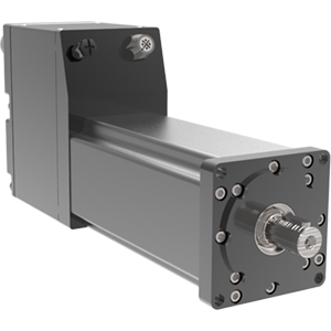
Tritex RDM/G DC Drehantrieb
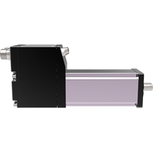
RDM Horizontal
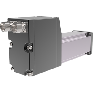
RDM Back
previous
next

Tritex RDM/G DC Drehantrieb

Intelligent Drive | Motor-| Stellglied

Industrial - Exlar

  • Einfache, eigenständige lineare Bewegungsachse.
  • Expert Konfigurationssoftware
  • Ausgangsdrehmoment bis zu 235 Nm (2078 lbf-in)
  • Drehzahlen bis zu 5000 U/min
  • Übersetzungen von 4:1 bis 100:1.
  • Spannungsklassen bis zu 48 V DC.
  • Optionen für Klasse 1 Division II (C1D2)
Mehr Details

Overview

Tritex RDM/G DC Drehantrieb

Schnelle Daten
Modell
Rahmengröße mm (in)
Übersetzungsverhältnis x:1
Max. Abtriebsdrehmoment (Getriebe) Nm (lbf)
Ausgangsdrehzahl (RPM)
RDM/G06060 (2.36)
4, 5, 10, 16, 20, 25, 40, 50,100
68.1 (603)5000/ratio
RDM/G07575 (2.95)
4, 5, 10
182.8 (1,618)4000/ratio
RDM/G09090 (3.54)
4, 5, 10, 16, 20, 25, 40, 50,100
234.8 (2,078)3300/ratio

Branchenführender DC-betriebener Drehantrieb

Der DC-betriebene Drehantrieb Tritex II beherbergt einen Servoantrieb, einen digitalen Positionierer und einen Servomotor in einem einzigen, kompakten Gehäuse. Diese fortschrittlichen Aktuatoren bieten die höchste Leistungsdichte und die geringste Stellfläche servogetriebener Geräte auf dem Markt. Ihre geringe Größe und ihr innovatives Design machen es einfach, eine vollelektronische Lösung in den Raum Ihres vorhandenen Hydraulik- oder Pneumatikzylinders zu integrieren. Jetzt können Sie Bewegungen präzise steuern und Ihre Anwendungsanforderungen mit einem einzigen, vollständig integrierten Gerät lösen.


Programmierbare Leistung und Leistung

Die DC-betriebenen Tritex II-Drehantriebe integrieren einen 750-W-Servoverstärker mit einem leistungsstarken Motion-Controller. Diese Rotationsmotoren und Getriebemotoren liefern konsequent ein hohes Ansprechverhalten und eine präzise Steuerung. Mit Ihrem PC können Sie den Aktuator schnell und einfach so programmieren, dass er einem analogen Signal (entweder Spannung oder Strom) folgt, das Ihr bevorzugtes Drehmoment, Ihre Geschwindigkeit oder Ihre bevorzugte Position darstellt. Übersetzungen von 4:1 bis 100:1 bieten ausreichend Leistung, um eine Vielzahl von Anwendungen zu erfüllen, die einen hohen Turndown und eine hohe Genauigkeit erfordern. Zu den Standardfunktionen gehören analoges Verfolgen für Position, zusammengesetzte Bewegungen, Bewegungsverkettung und individuelle Drehmomentsteuerung für jede Bewegung. Tritex II ist die ideale Lösung für die meisten Motion-Control-Anwendungen.


Kompakte Größe und niedrige Betriebskosten

Diese robuste Drehantriebslösung bietet herausragende Zuverlässigkeit und Leistung und zeichnet sich durch einen kleinen Formfaktor aus. Mit dem Servoantrieb und dem digitalen Positionierer, die in einem einzigen, abgedichteten Gehäuse untergebracht sind, wird der Platzbedarf minimiert. Das innovative integrale Design eliminiert Arbeitskosten, die mit Montage- und Verdrahtungsplatten verbunden sind. Diese Lösung erfordert lediglich ein wirtschaftliches DC-Netzkabel und ein Standard-Kommunikationskabel für digitale und analoge I/O. Es besteht auch keine Notwendigkeit für teure, wartungsintensive Servokabel, und die damit verbundenen Signalprobleme über große Entfernungen gehören der Vergangenheit an.


Weitere Vorteile

  • Maximale Leistung, Präzision und Geschwindigkeit in einem kompakten Paket
  • Gleichstromelektronik für mobile und/oder batteriebetriebene Anwendungen
  • Überlegener Ersatz für Pneumatik- und Hydraulikzylinder 
  • Programmierbare Software ermöglicht automatisierte Sequenzierung
  • Schutzart IP66S für den Einsatz in rauen Umgebungen
  • Mehrere Feedback-Typen für jede Anwendung
  • Digitale und analoge I/O und gängige Kommunikationsnetzwerke
  • Entwickelt für Closed-Loop-Servosysteme
  • 100% Tastverhältnis für Hunderte von Millionen Hub 
  • Abgedichtetes Gehäuse für längere Lebensdauer und reduzierten Wartungsaufwand 

Verwandte Branchen

Quick Data
Models:RDM rotary motor
RDG rotary gearmotor
Frame Sizes: 2.4, 3, 3.5 in (60, 75, 90 mm)
Gear Ratios:4:1, 5:1, 10:1, 16:1, 20:1, 25:1, 40:1, 50:1, 100:1
Maximum Output Torque:up to 2078 lbf-in (235 Nm)
Output Speeds:3300, 4000, 5000 rpm per gear ratio
Standards/RatingsCE; UL 508 C Type 4 Enclosure; CSA 139; CSA Class I Division 2 Groups A, B, C, and D; IP66S standard; IEC 61800-5-1 safety standard for drives

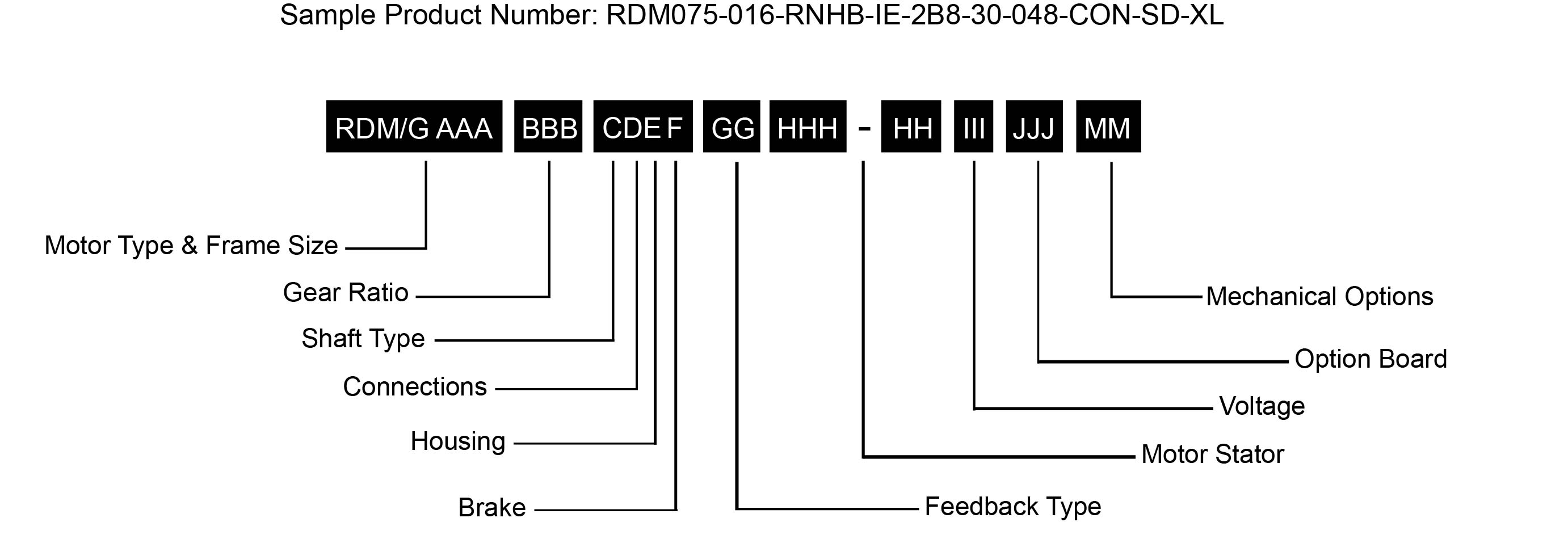
RDM/G = Motor Type
RDM = Tritex II DC Rotary Motor  
RDG = Tritex II DC Rotary Gearmotor

AAA = Frame Size
060 = 60 mm
075 = 75 mm
090 = 90 mm

BBB = Gear Ratio
Blank = RDM
Single Reduction Ratios 
004 = 4:1    005 = 5:1    010 = 10:1
Double Reduction Ratios (NA on 75 mm)
016 = 16:1    020 = 20:1
025 = 25:1    040 = 40:1
050 = 50:1    100 = 100:1

C = Shaft Type
K = Keyed

D = Connections
G = Standard straight threaded port with internal terminals, M20x1.5 (75 & 90 mm only)
N = NPT threaded port internal terminals, 1/2”  NPT (75 & 90 mm only)
I = Intercontec style – Exlar standard, M23 Style Connector

E = Housing Options
G = Exlar Standard

F = Brake Options
S = No Brake, Standard
B = Electric Brake, 24 VDC

GG = Feedback Type
HD = Analog Hall Device
IE = Incremental Encoder, 8192 Count Resolution
AF = Absolute Feedback3

HHH-HH = Motor Stators - All 8 Pole
RDM/G060 Stator Specifications 
1B8-50 = 1 Stack, 48 Vdc, 5000 rpm
2B8-50 = 2 Stack, 48 Vdc, 5000 rpm
3B8-40 = 3 Stack, 48 Vdc, 4000 rpm

RDM/G075 Stator Specifications 
1B8-40 = 1 Stack, 48 Vdc, 4000 rpm
2B8-30 = 2 Stack, 48 Vdc, 3000 rpm
3B8-20 = 3 Stack, 48 Vdc, 2000 rpm

RDM/G090 Stator Specifications 
1B8-33 = 1 Stack, 48 Vdc, 3300 rpm
2B8-18 = 2 Stack, 48 Vdc, 1800 rpm
3B8-14 = 3 Stack, 48 Vdc 1400 rpm

III = Voltage
048= 12-48 Vdc

JJJ = Option Board
SIO = Standard I/O Interconnect
IA4 = + 4-20 mA Analog I/O
EIP = SIO plus EtherNet/IP with M12 connector
EIN = SIO plus EtherNet/IP without M12 connector2
PIO = SIO plus PROFINET IO w/M12 connector
PIN = SIO plus PROFINET IO without M12 connector2
TCP = SIO plus Modbus TCP w/M12 connector
TCN = SIO plus Modbus TCP without M12 connector2


Standard Features
Analog and digital I/O
Built-in positioner
Internal terminals accessible through removable cover (on 75 and 90 mm models)
Threaded ports for cable glands (on 75 and 90 mm models)
M12 connector for Ethernet options
RS485 port (M8), Modbus RTU (opto-isolated)


NOTIZEN :
1. Für einen längeren Temperaturbetrieb wenden Sie sich bitte an das Werk für die Modellnummer.
2. Erfordert vom Kunden geliefertes Ethernet-Kabel über den E/A-Port nur für die Konformität der Klasse 1 Division 2. Auch N/A auf 60 mm.
3. Bei der Bestellung eines TDM, RDM oder RDG 60 mm oder anderer Größen mit oben montierten Anschlüssen muss das Batterie-Backup für AF-Feedback extern montiert werden. Eine Hutschienenplatine (Exlar PN 48224) und Batterie (PN T2BAT2) werden mitgeliefert. 

* Einige Optionen sind nicht mit jeder Konfiguration verfügbar. Für Optionen oder Specials, die oben nicht aufgeführt sind, wenden Sie sich an Ihren lokalen Exlar vertreter.

Product Spezifikationen

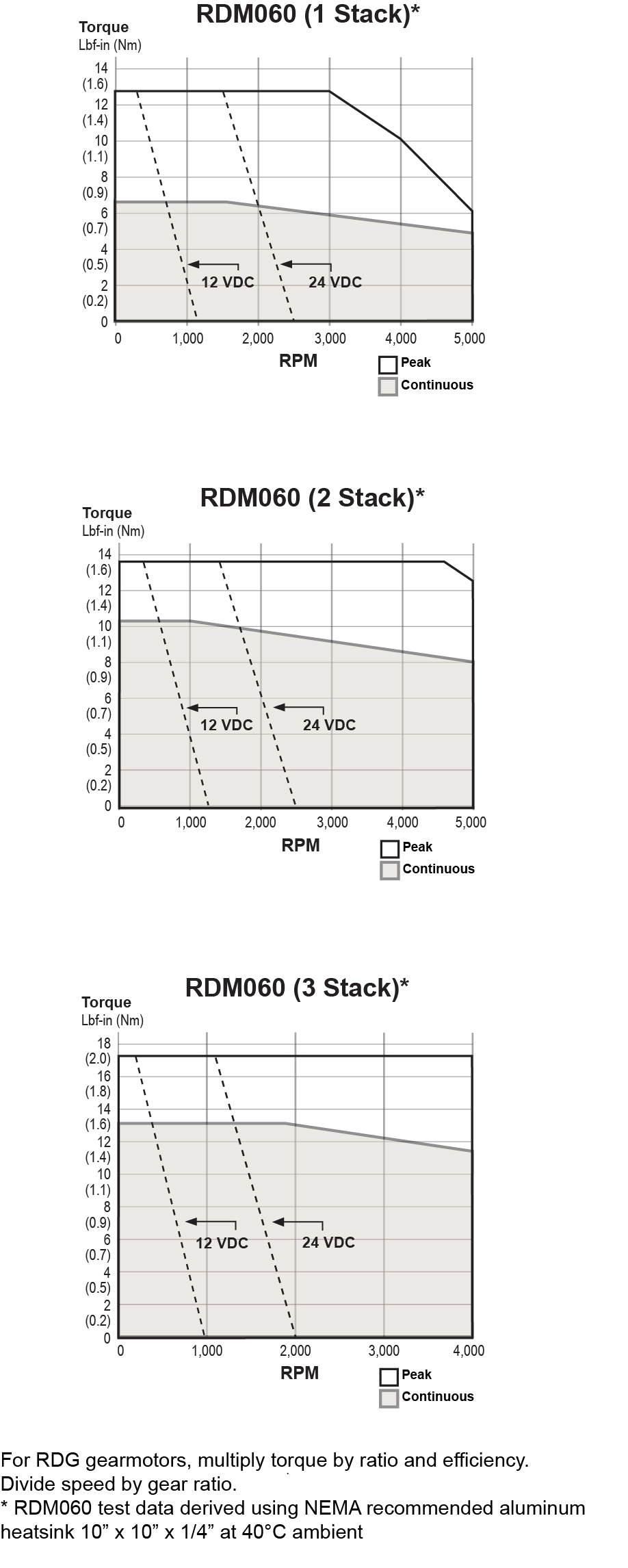
RDM/G060 LeistungsbeschreibungenOpen arrow

RDM/G060 Rotary Torque and Speed Ratings

  STATOR 1 STACK 2 STACK 3 STACK
  RPM at 48 VDC 5000 5000 4000
Continuous Torque lbf-in (Nm) 6.8 (0.76) 10.5 (1.18) 13 (1.47)
Peak Torque lbf-in (Nm) 12.8 (1.44) 13.3 (1.5) 17 (1.92)
Drive Current @ Continuous Torque Amps 14.8 21.5 21.5
Operating Temperature Range** 
(-40˚C available, consult Exlar)
-20 to 65˚ C
Maximum Continuous Power Supply Current* Amps 8 11 13

*Power supply current is based on software current limit, not thermal limit. Consideration for peak current should also be considered when sizing power supplies. For output torque of RDG gearmotors, multiply by ratio and efficiency. Please note maximum allowable output torques found at bottom of page.
**Ratings based on 40˚ C ambient conditions.


RDM/G060 Inertia

  STATOR 1 STACK 2 STACK 3 STACK
RDM Motor Armature Inertia (+/-5%) lb-in-sec^2 (kg-cm^2) 0.000237 (0.268) 0.000413 (0.466) 0.000589 (0.665)
RDG Gearmotor Armature Inertia* lbf-in-sec^2 (kg-cm^2) 0.000226 (0.255) 0.000401 (0.453) 0.000576 (0.651)

*Add armature inertia to gearing inertia for total inertia.


RDM/G060 Radial Load Bearing Life

RPM 50 100 250 500 1000 3000
RDM060 lbf (N) 250 (1112) 198 (881) 148 (658) 116 (516) 92 (409) 64 (285)
RDG060 lbf (N) 189 (841) 150 (667) 110 (489) 88 (391) 70 (311) 48 (214)

Side load ratings shown above are for 10,000 hour bearing life at 25 mm from motor face at given rpm.


RDM/G060 Gearmotor Mechanical Ratings

MODEL RATIO MAXIMUM ALLOWABLE OUTPUT 
TORQUE-SET BY USER LBF-IN (NM)
1000 RPM LBF-IN (NM) 3000 RPM LBF-IN (NM) 5000 RPM LBF-IN (NM)
RDG060-004 4:1 603 (68.1) 144 (16.2) 104 (11.7) 88 (9.9)
RDG060-005 5:1 522 (58.9) 170 (19.2) 125 (14.1) 105 (11.9)
RDG060-010 10:1 327 (36.9) 200 (22.6) 140 (15.8) 120 (13.6)
RDG060-016 16:1 603 (68.1) 224 (25.3) 160 (18.1) 136 (15.4)
RDG060-020 20:1 603 (68.1) 240 (27.1) 170 (19.2) 146 (16.5)
RDG060-025 25:1 522 (58.9) 275 (31.1) 200 (22.6) 180 (20.3)
RDG060-040 40:1 603 (68.1) 288 (32.5) 208 (23.5) 180 (20.3)
RDG060-050 50:1 522 (58.9) 340 (38.4) 245 (27.7) 210 (23.7)
RDG060-100 100:1 327 (36.9) 320 (36.1) 280 (31.6) 240 (27.1)

Output Torque at Motor Speed for 10,000 Hour Life. Two torque ratings for the RDG gearmotors are given in the table above. The left hand columns give the maximum (peak) allowable output torque for the indicated ratios of each size RDG gearmotor. This is not the rated output torque of the motor multiplied by the ratio of the reducer. It is possible to select a configuration of the motor selection and gear ratio such that the rated motor torque, multiplied by the gear ratio exceeds these ratings. It is the responsibility of the user to ensure that the settings of the system do not allow these values to be exceeded. The right hand columns give the output torque at the indicated speed which will result in 10,000 hour life (L10). The setup of the system will determine the actual output torque and speed.


RDM/G060 Gearing Reflected Inertia

GEAR STAGES LBF-IN-SEC^2 (KG-CM^2)
Single Reduction
4:1 0.0000132 (0.149)
5:1 0.0000087 (0.00984)
10:1 0.0000023 (0.00261)
Double Reduction
16:1 0.0000121 (0.0137)
20:1, 25:1 0.0000080 (0.00906)
40:1, 50:1, 100:1 0.0000021 (0.00242)


RDM/G060 Backlash and Efficiency

  SINGLE REDUCTION DOUBLE REDUCTION
Backlash at 1% Rated Torque 10 Arc min 13 Arc min
Efficiency 91% 86%


RDM/G060 Motor and Gearmotor Weights

  RDM060 WITHOUT GEARS RDG060 WITH 1 STAGE GEARING RDG060 WITH 2 STAGE GEARING ADDED WEIGHT FOR BRAKE
1 Stack Stator lb (kg) 3.0 (1.4) 7.5 (3.4) 9.3 (4.2) 0.6 (0.3)
2 Stack Stator lb (kg) 4.1 (1.9) 8.6 (3.9) 10.4 (4.7) 0.6 (0.3)
3 Stack Stator lb (kg) 5.2 (2.4) 9.7 (4.4) 11.5 (5.2) 0.6 (0.3)
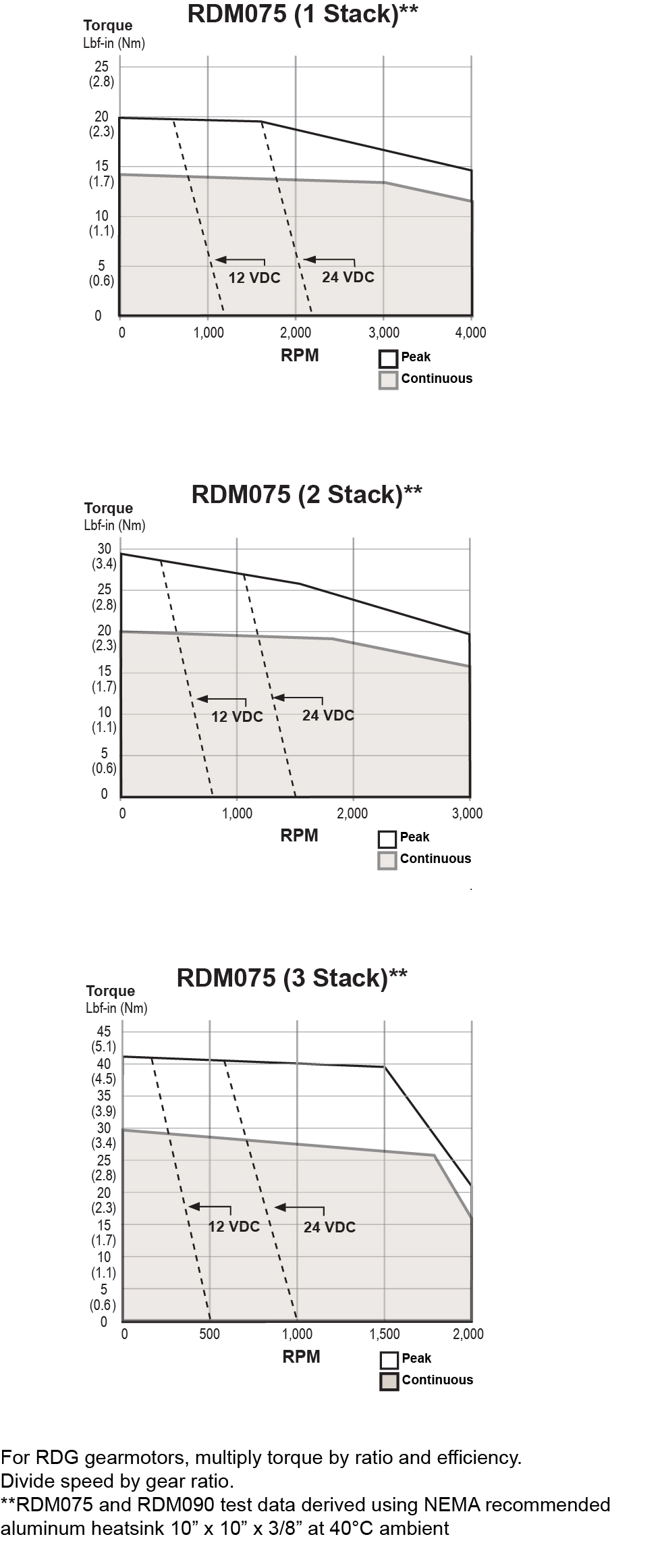
RDM/G075 LeistungsbeschreibungenOpen arrow

RDM/G075 Rotary Motor Torque and Speed Ratings

  STATOR 1 STACK 2 STACK 3 STACK
  RPM at 48 VDC 4000 3000 2000
Continuous Torque lbf-in (Nm) 13 (1.46) 18.5 (2.09) 29 (3.28)
Peak Torque lbf-in (Nm) 18.9 (2.08) 28 (3.16) 41 (4.63)
Drive Current @ Continuous Torque Amps 22 22 22
Operating Temperature Range** 
(-40˚C available, consult Exlar)
-20 to 65˚ C
Maximum Continuous Power Supply Current* Amps 15 18 18

*Power supply current is based on software current limit, not thermal limit. Consideration for peak current should also be considered when sizing power supplies. For output torque of RDG gearmotors, multiply by ratio and efficiency. Please note maximum allowable output torques shown below. 
**Ratings based on 40˚ C ambient conditions.


RDM/G075 Inertia

  STATOR 1 STACK 2 STACK 3 STACK
RDM Motor Armature Inertia (+/-5%) lb-in-sec^2 (kg-cm^2) 0.000545 (0.6158) 0.000973 (1.0996) 0.001401 (1.5834)
RDG Gearmotor Armature Inertia* (+/-5%) lbf-in-sec^2 (kg-cm^2) 0.000660 (0.7450) 0.001068 (1.2057) 0.001494 (1.6868)

*Add armature inertia to gearing inertia for total inertia.


RDM/G075 Radial Load and Bearing Life

RPM 50 100 250 500 1000 3000
RDM075 lbf (N) 278 (1237) 220 (979) 162 (721) 129 (574) 102 (454) 71 (316)
RDG075 lbf (N) 343 (1526) 272 (1210) 200 (890) 159 (707) 126 (560) 88 (391)

*Side load ratings shown above are for 10,000 hour bearing life at 25 mm from motor face at given rpm.


RDM/G075 Gearmotor Mechanical Ratings

MODEL RATIO MAXIMUM ALLOWABLE OUTPUT 
TORQUE-SET BY USER LBF-IN (NM)
1000 RPM LBF-IN (NM) 2500 RPM LBF-IN (NM) 4000 RPM LBF-IN (NM)
RDG075-004 4:1 1618 (182.8) 384 (43.4) 292 (32.9) 254 (28.7)
RDG075-005 5:1 1446 (163.4) 395 (44.6) 300 (33.9) 260 (29.4)
RDG075-010 10:1 700 (79.1) 449 (50.7) 341 (38.5) 296 (33.4)

Output Torque at Motor Speed for 10,000 Hour Life. Two torque ratings for the RDG gearmotors are given in the table above. The left hand columns give the maximum (peak) allowable output torque for the indicated ratios of each size RDG gearmotor. This is not the rated output torque of the motor multiplied by the ratio of the reducer. It is possible to select a configuration of the motor selection and gear ratio such that the rated motor torque, multiplied by the gear ratio exceeds these ratings. It is the responsibility of the user to ensure that the settings of the system do not allow these values to be exceeded. The right hand columns give the output torque at the indicated speed which will result in 10,000 hour life (L10). The setup of the system will determine the actual output torque and speed.


RDM/G075 Gearing Reflected Inertia

SINGLE REDUCTION (+/-5%)    
Gear Stages lbf-in-sec^2 (kg-cm^2)
4:1 0.000095 (0.107)
5:1 0.000062 (0.069)
10:1 0.000117 (0.019)


RDM/G075 Backlash and Efficiency

  SINGLE REDUCTION
Backlash at 1% Rated Torque 10 Arc min
Efficiency 91%


RDM/G075 Motor and Gearmotor Weights

  RDM075 WITHOUT GEARS RDG075 WITH 1 STAGE GEARING ADDED WEIGHT FOR BRAKE
1 Stack Stator lb (kg) 7.4 (3.4) 9.8 (4.4) 1.0 (0.5)
2 Stack Stator lb (kg) 9.2 (4.2) 11.6 (5.3) 1.0 (0.5)
3 Stack Stator lb (kg) 11 (4.9) 13.4 (6.1) 1.0 (0.5)
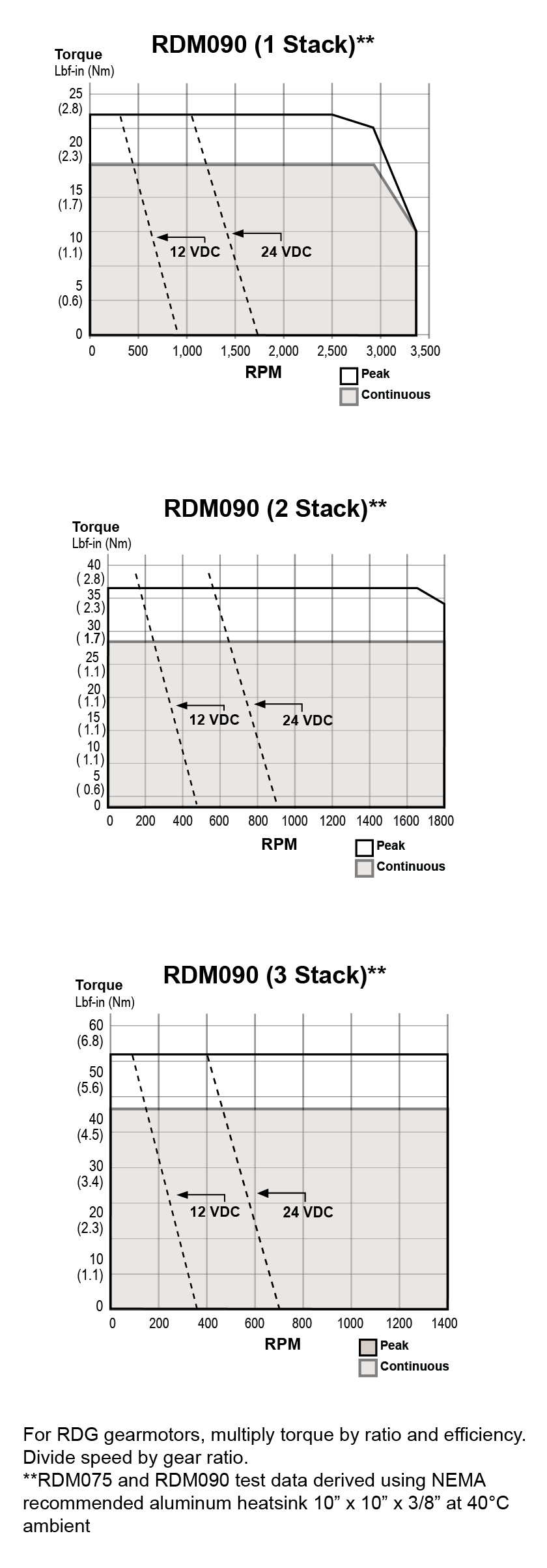
RDM/G090 LeistungsbeschreibungenOpen arrow

RDM/G090 Rotary Motor Torque and Speed Ratings

  STATOR 1 STACK 2 STACK 3 STACK
  RPM at 48 VDC 3300 1800 1400
Continuous Torque lbf-in (Nm) 17 (1.92) 28 (3.16) 41 (4.63)
Peak Torque lbf-in (Nm) 21.8 (2.46) 36 (4.07) 52.8 (5.97)
Drive Current @ Continuous Torque Amps 22 22 22
Operating Temperature Range** 
(-40˚C available, consult Exlar)
-20 to 65˚ C
Maximum Continuous Power Supply Current* Amps 18 18 18

*Power supply current is based on software current limit, not thermal limit. Consideration for peak current should also be considered when sizing power supplies. For output torque of RDG gearmotors, multiply by ratio and efficiency. Please note maximum allowable output torques shown below.
**Ratings based on 40˚ C ambient conditions.


RDM/G090 Inertia

  STATOR 1 STACK 2 STACK 3 STACK
RDM Motor Armature Inertia (+/-5%) lb-in-sec^2 (kg-cm^2) 0.00054 (0.609) 0.00097 (1.09) 0.00140 (1.58)
RDG Gearmotor Armature Inertia* (+/-5%) lbf-in-sec^2 (kg-cm^2) 0.00114 (1.29) 0.00157 (1.77) 0.00200 (2.26)

*Add armature inertia to gearing inertia for total inertia.


RDM/G090 Radial Load and Bearing Life

RPM 50 100 250 500 1000 3000
RDM090 lbf (N) 427 (1899) 340 (1512) 250 (1112) 198 (881) 158 (703) 109 (485)
RDG090 lbf (N) 350 (1557) 278 (1237) 205 (912) 163 (725) 129 (574) 89 (396)

Side load ratings shown above are for 10,000 hour bearing life at 25 mm from motor face at given rpm.


RDM/G090 Gearmotor Mechanical Ratings

MODEL RATIO MAXIMUM ALLOWABLE OUTPUT 
TORQUE-SET BY USER LBF-IN (NM)
1000 RPM LBF-IN (NM) 2500 RPM LBF-IN (NM) 3300 RPM LBF-IN (NM)
RDG090-004 4:1 2078 (234.8) 698 (78.9) 530 (59.9) 488 (55.1)
RDG090-005 5:1 1798 (203.1) 896 (101.2) 680 (76.8) 626 (70.7)
RDG090-010 10:1 1126 (127.2) 1043 (117.8) 792 (89.5) 729 (82.4)
RDG090-016 16:1 2078 (234.8) 1057 (119.4) 803 (90.7) 739 (83.5)
RDG090-020 20:1 2078 (234.8) 1131 (127.8) 859 (97.1) 790 (89.3)
RDG090-025 25:1 1798 (203.1) 1452 (164.1) 1103 (124.6) 1015 (114.7)
RDG090-040 40:1 2078 (234.8) 1392 (157.3) 1057 (119.4) 973 (109.9)
RDG090-050 50:1 1798 (203.1) 1787 (201.9) 1358 (153.4) 1249 (141.1)
RDG090-100 100:1 1126 (127.2) 1100 (124.3) 1100 (124.3) 1100 (124.3)

Output Torque at Motor Speed for 10,000 Hour Life.Two torque ratings for the RDG gearmotors are given in the table above. The left hand columns give the maximum (peak) allowable output torque for the indicated ratios of each size RDG gearmotor. This is not the rated output torque of the motor multiplied by the ratio of the reducer. It is possible to select a configuration of the motor selection and gear ratio such that the rated motor torque, multiplied by the gear ratio exceeds these ratings. It is the responsibility of the user to ensure that the settings of the system do not allow these values to be exceeded. The right hand columns give the output torque at the indicated speed which will result in 10,000 hour life (L10). The setup of the system will determine the actual output torque and speed.


RDM/G090 Gearing Reflected Inertia

GEAR STAGES LBF-IN-SEC^2 (KG-CM^2)
Single Reduction
4:1 0.0000154 (0.174)
5:1 0.0000100 (0.113)
10:1 0.0000265 (0.0300)
Double Reduction
16:1 0.000115 (0.130)
20:1, 25:1 0.0000756 (0.0854)
40:1, 50:1, 100:1 0.0000203 (0.0230)


RDM/G090 Backlash and Efficiency

  SINGLE REDUCTION DOUBLE REDUCTION
Backlash at 1% Rated Torque 10 Arc min 13 Arc min
Efficiency 91% 86%


RDM/G090 Motor and Gearmotor Weights

  RDM090 WITHOUT GEARS RDG090 WITH 1 STAGE GEARING RDG090 WITH 2 STAGE GEARING ADDED WEIGHT FOR BRAKE
1 Stack Stator lb (kg) 12.5 (5.7) 20.5 (9.3) 23.5 (10.7) 1.5 (0.7)
2 Stack Stator lb (kg) 15.5 (7.0) 23.5 (10.7) 26.5 (12) 1.5 (0.7)
3 Stack Stator lb (kg) 18.5 (8.4) 26.5 (12.0) 29.5 (13.4) 1.5 (0.7)

Produktliteratur

Kataloge, Broschüren und Erfolgsgeschichten

Industrial - Exlar, Broschüren / Kataloge
Industrial - Exlar
Industrial - Exlar, Broschüren / Kataloge
Industrial - Exlar
Industrial - Exlar
Industrial - Exlar, Success Stories
Die Exlar Corporation bot nicht nur die richtigen Aktuatoren, sondern auch das anwendungstechnische Know-how, um alle Designanforderungen von Circonix zu erfüllen.
Industrial - Exlar, Betätigungslösungen
Umweltfreundliche Exlar-Aktuatoren bieten die gleiche Ansprechzeit wie bestehende pneumatische Aktuatoren und können bei Temperaturen von -40 ° C bis 65 ° C installiert werden.
Show Resources

Technische Daten des Aktuators

Handbücher und technische Tipps

Industrial - Exlar, Bedienungsanleitungen
Industrial - Exlar, Software & Downloads
Industrial - Exlar, Bedienungsanleitungen
Industrial - Exlar, Technische Tipps für Stellantriebe
Industrial - Exlar, Bedienungsanleitungen
Industrial - Exlar, Technische Tipps für Stellantriebe
Show Resources

Videos

Industrial - Exlar, Produktvideos
Unsere Automotive Factory Floor Solutions Animation zeigt unsere FTX-, GTX-, GTW- und TTX-Aktuatoren und wo sie Fabriken weltweit helfen können.
Industrial - Exlar, Produktvideos
https://www.youtube.com/watch?v=ap4JVgUBpjY&t=3s
Show Resources

Weitere Ressourcen finden Sie in unserem InfoCenter.  

Wie können wir helfen?

Können die Tritex II Linearantriebe Hydraulikzylinder ersetzen?Arrow
Tritex-Aktuatoren haben ähnliche Fähigkeiten wie vergleichbar große Hydraulikzylinder, jedoch ohne Kosten oder Wartungsprobleme. Hohe Kraft, hohe Geschwindigkeiten und präzise Bewegungen machen es zu einem überlegenen Ersatz für hydraulische Anwendungen.
Ist der AC-Linearantrieb ein idealer hydraulischer Ersatz?Arrow
Tritex-Aktuatoren haben die gleichen Fähigkeiten wie ein hydraulisches Äquivalent, jedoch ohne Kosten oder Wartungsprobleme. Hohe Kraft, hohe Geschwindigkeiten und präzise Bewegungen machen es zu einem überlegenen Ersatz für hydraulische Anwendungen.
Ist die Tritex-Serie ein Industrie 4.0 IoT-Aktuator?Arrow

Die Aktuatoren der Tritex II-Serie sind intelligente Aktuatoren mit integrierten Steuerungs- und Kommunikationsfunktionen, die die Unterstützung von verteilter Steuerung und IIoT-Architekturen ermöglichen. Daraus ergibt sich:

  • Produktionseffizienz (Geschwindigkeit, Betriebszeit, Arbeitszyklus)
  • Ökologische Nachhaltigkeit (Energieeffizienz, Reduzierung von Gefahrstoffen)
  • Agile und anpassungsfähige Prozesse (Konfigurierbarkeit, Konnektivität)
  • Vollständig autonomer Betrieb (verteilte Steuerung, vorausschauende Wartung)
Was sind die Hauptvorteile der Verwendung eines elektrischen Aktuatorsystems gegenüber der Hydraulik?Arrow
Elektrische Aktuatoren bieten hohe Geschwindigkeit und Kraft, sind flexibel und leicht programmierbar für eine Vielzahl von Lastbedingungen, haben eine hohe Genauigkeit und Wiederholbarkeit, sind effizient, einfach zu installieren, erfordern wenig Wartung und sind umweltfreundlich.
 
Durch den Verzicht auf ein Hydrauliksystem kann der Benutzer Öllecks beseitigen, die Umweltverschmutzung reduzieren und die Sicherheit der Arbeitnehmer verbessern. Elektrische Aktuatoren sind auch eine ungiftige Lösung, insbesondere in der Lebensmittelindustrie.
 

This site uses cookies to improve our service, you can find out more here - for the best web experience please accept cookies

x